


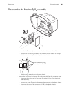

86 Disassembly procedure Welch Allyn VSM 300 Series
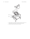
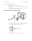
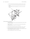
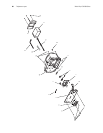
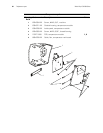
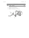
d. Remove the three screws (C) securing the circuit board to the plastic chassis.
e. Remove the two screws (D) securing the SpO2 sensor flex to the connector
housing.
f. Slide the SpO2 sensor flex cable assembly out of the rails on the connector
housing.
SpO
2
reassembly notes (Masimo)
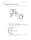
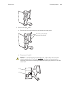
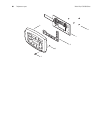
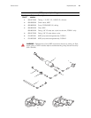
1. Place the SpO2 sensor flex into the connector housing and secure it with two screws
(D). (Torque = 4 lbf-in.)
2. Place the circuit board (C) into the plastic chassis and secure it with three screws.
(Torque = 4 lbf-in.)
3. Connect the sensor flex connector to the circuit board at J1.
4. Fasten the sensor flex connector in place with one screw (B) . (Torque = 4 lbf-in.)
5. Connect the mating end of the power flex cable (A) to J3 on the circuit board.
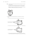
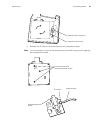
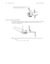
6. Slide the SpO2 assembly into place in the monitor rear chassis, seating the rail of the
connector housing into the slots in the rear chassis.
7. Secure the SpO2 panel with four screws. (Torque = 4 lbf-in.)
D
A
B
C