


56 Disassembly procedure Welch Allyn VSM 300 Series
Connectors
Connector types
The procedures described below require you to disconnect and reconnect ZIF (zero-
insertion force) connectors, squeeze-release connectors, and pressure connectors.
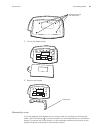
Zero-insertion force (ZIF) flex-cable connectors
ZIF flex-cable connectors include J1 on the display board, CN2 on the printer board, J1 on
the temperature board, and J5 and J12 on the main board.
ZIF connectors use a sliding outer piece that latches and unlatches to secure and release
the flex cable.
• To release a ZIF cable, slide the latching piece of the connector away from the
connector body and toward the cable; the cable can then be removed without
effort.
• To connect a ZIF cable, slide the latching piece of the connector body toward the
cable, insert the flex cable easily into the connector, and slide the latching piece
back toward the connector body until it clicks into place.
Side-release connectors
Side-release connectors include J7 and J9 on the main board and J2 on the NIBP board.
To use side-release connectors, squeeze the sides of the connectors to insert or remove
the cables.
Pressure connectors
Pressure connectors include and CN1 and CN3 on the printer board; J2, J3, J4, J6, J8,
J10, and J11 on the main board; J1 and J2 on the SpO
2
board.
To use pressure connectors, grasp each mating connector half and pull the halves apart or
insert one half into the other.
Main board connectors
For the best results when disconnecting cables from the main board, disconnect the
upper cables first and work your way to the bottom of the board, in approximately the
following order:
Caution All connectors are keyed or coded to facilitate proper connection. Take
care to correctly align all connector halves before attempting to connect them.
Caution Do not attempt to remove a flex cable until the ZIF latch has been
opened.
Caution Never attempt to disconnect cables by pulling on the wires. Always
disconnect cables by grasping and pulling only on the connector halves.
Note
See the illustration in “Main board reassembly notes” on page 66.