


5
55
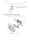
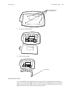
Disassembly procedure
Procedures overview
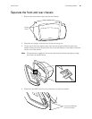
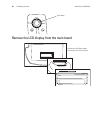
These procedures cover monitor disassembly and board removal. Unless otherwise
noted, the assembly procedure is the reverse of the disassembly procedure.
Screws
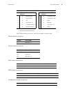
Following are recommended torque specs for all screws:
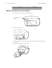
WARNING Electrical shock hazard. The battery can deliver currents sufficient to
cause serious personal injury and to damage the monitor. When opening the
monitor for any reason, always remove and disconnect the battery immediately,
before proceeding with disassembly.
Caution Do all repairs at a static-protected station.
Caution Observe recommended screw torque specifications, especially with
screws that secure directly into plastic standoffs.
Caution To avoid mismatching screws and holes, keep the screws for each
piece with that piece as you remove modules, circuit assemblies, and other
components.
Qty Location Part Number Type Size/length Torque
4 Battery Door 620-0399-00 Machine #4-40, 5/16” 4 lbf/in.
3 Case 620-0399-00 Machine #4-40, 5/16” 4 lbf/in.
5 Display Board 620-0393-00 Thread-forming #4-20, 5/16” 4 lbf/in.
4 Main Board 620-0393-00 Thread-forming #4-20, 5/16” 4 lbf/in.
4 NIBP Board 620-0393-00 Thread-forming #4-20, 5/16” 4 lbf/in.
4 SpO
2
Panel 620-0393-00 Thread-forming #4-20, 5/16” 4 lbf/in.
2 SpO
2
Board 620-0047-00 Machine #6-32, 1/4” 4 lbf/in.
2 Printer 620-0165-00 Thread-forming #2-28, 5/16” 3 lbf/in.
1 Printer Board 620-0165-00 Thread-forming #2-28, 5/16” 3 lbf/in.
2 Printer door/roller 620-0091-00 Thread-forming #2-32, 3/16” 3 lbf/in.
2 Temp. Module 620-0394-00 Machine #4-40, 3/4” 4 lbf/in.
4 Temp. Panel 620-0393-00 Thread-forming #4-20, 5/16” 4 lbf/in.
4 Temp Board 620-0393-00 Thread-forming #4-20, 5/16” 4 lbf/in.