


Service manual Functional verification 27
Nurse call
Relay verification
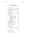
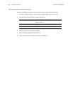
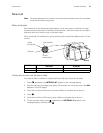
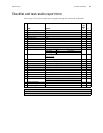
With reference to the drawing and table below, use an ohmmeter to check the contact
resistance at the output pins of the Nurse Call connector, while the monitor is in the alarm
state and while the monitor is out of the alarm state.
When the Nurse Call verification is done, disconnect the Nurse Call cable and turn off the
monitor.
Putting the monitor into the alarm state
To create an alarm condition for testing the Nurse Call relay, follow these steps.
1. Press repeatedly until INTERVAL ST appears in the message display.
2. Wait for the pump to charge twice (about 10 seconds), and verify that error code C04
appears in the SYS display.
3. Verify that the Nurse Call circuit is shorted. (Refer to the table shown above.)
4. Press .
5. Verify that the Nurse Call circuit is open. (Refer to the table shown above.)
6. To exit the alarm state, press repeatedly until INTERVAL 15 appears in the
message display, and then press .
Note
The tests described in this section are to be performed only as part of a complete
functional verification procedure.
Pins Resistance
(Alarm OFF)
Resistance
(Alarm ON)
1-2 > 1 M <1
2-3 < 1 >1M
30V , 1A Max.
1 (Black)
Normally Open
4 (not connected)
3 (Green)
Normally Closed
2 (Red) Arm