


Service manual Disassembly procedure 75
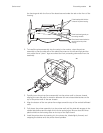
the housing and with the front of the board secured under the tab on the front of the
housing.
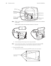
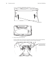
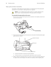
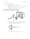
2. To install the printer assembly into the cavity in the monitor, orient the printer
assembly so that the side rails of the plastic frame are on the left and right and the
two printer-frame “piano” legs are toward the front, extending downward from the
assembly.
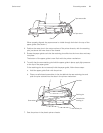
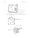
3. Partially insert the printer frame assembly into the printer well in the rear chassis,
aligning the rear side rails for insertion between the two slotted side latches on the
top of the printer well of the rear chassis.
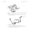
4. Align the bottom of the two printer frame legs toward the top of the vertical bulkhead
slots.
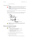
5. Fully insert the printer assembly into the printer well until the side rails engage in the
slotted side latches and the legs click into the vertical slots. Be sure that the white
plastic shield on the housing rests on the top of the SpO
2
board.
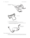
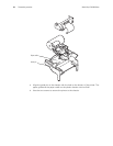
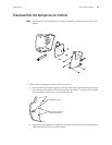
6. Install the printer door by inserting it in the printer slot, tilted slightly forward, and
snapping the latches onto the printer frame spindles.
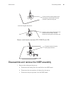
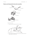
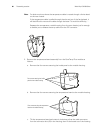
Printer board parallel with the
surface of the printer housing.
Printer board inserted under the
retaining tab on the printer
housing.
Printer board resting evenly on
the housing standoffs.