


Service manual Disassembly procedure 65
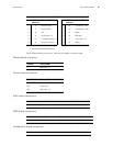
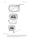
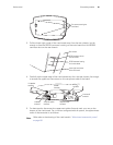
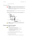
3. Pull the lower right corner of the main board away from the rear chassis, just far
enough to free the RS232 connector housing on the main board from the RS232
connector slot on the rear chassis.
4. Carefully tip the upper edge of the main board away from the rear chassis, far enough
to access the uppermost connectors on the component side of the board.
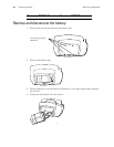
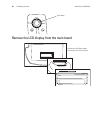
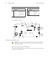
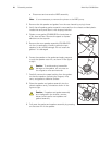
5. For best results, disconnect the uppermost cables first and work your way to the
bottom of the main board. For a monitor configured with all options, the approximate
order of disconnection is as follows:
Note
Refer also to the drawing of the main board in “Main board reassembly notes”
on page 66.
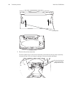
Four screws securing the
main board
Lower right-hand corner
of the main board
RS232connector housing
on the main board
RS232 connector slot on
the rear chassis
Rear chassis
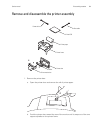
J3 battery
connector
J10 printer power
connector
J8 printer cable
connector
J4 nurse call
connector
J11 speaker
connector
J9 NIBP
connector
J7 SpO
2
connector