


46
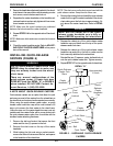
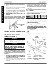
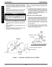
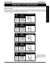
3. Position the anti-tipper mounting bracket between
the two (2) half clamps. Make sure the release
button holes are pointing towards the front of the
wheelchair.
4. Secure the mounting bracket to the two (2) half
clamps with two (2) hex screws and locknuts.
5. Securely tighten the top hex screw and locknut.
WARNING
Anti-tippers MUST be fully engaged and
release buttons fully protruding out of re-
lease button holes BEFORE using wheel-
chair.
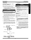
6. Press down on the release buttons of the anti-tip-
per and insert the anti-tipper into the anti-tipper
mounting bracket until the release buttons lock in
place.
7. Repeat STEPS 1-6 for the opposite side of the
wheelchair.
8. Measure the distance between the bottom of the
anti-tipper wheel and the ground/floor.
NOTE: A 1-1/2 to 2-inch clearance between the bot-
tom of the anti-tipper wheels and the floor must be
maintained.
9. If the distance between the bottom of the anti-tip-
per wheel and the ground/floor is not between 1-1/
2 to 2-inches, adjust the anti-tipper. Refer to AD-
JUSTING THE ANTI-TIPPER HEIGHT in this
procedure of the manual.
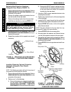
Adjusting the Anti-tipper Height
1. Loosen, but do not remove the three (3) hex screws
and locknuts that secure the half clamps and anti-
tipper mounting brackets to the wheelchair frame.
2. Slide the half clamps forward or rearward along
the wheelchair frame until the 1-1/2 to 2-inch clear-
ance is achieved.
3. Securely tighten the three (3) hex screws that se-
cure the half clamps and anti-tipper mounting
brackets to the wheelchair frame.
1-1/2 to 2-inch Clearance
Release
Button
Adjust
Height
Anti-tipper Mounting Bracket
Release Buttons
Anti-tipper
Anti-tipper
Mounting Bracket
Wheelchair Frame
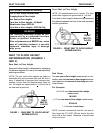
FIGURE 13 - INSTALLING/ADJUSTING THE ANTI-TIPPERS
Half
Clamps
Wheelchair
Frame
Hex
Screws
Locknuts
Anti-tipper
Anti-tipper
Mounting
Bracket
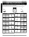
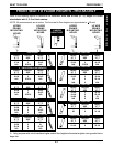
PROCEDURE 6 REAR WHEELS
R
E
A
R
W
H
E
E
L
S