


28
5. Reinstall the half arm into the arm socket.
6. Repeat STEPS 1-5 for the opposite side, if nec-
essary.
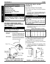
NOTE: If desired height is still not obtainable, reposi-
tion the arm socket on the wheelchair with the top hex
screw in the top mounting hole of the arm socket and
the bottom hex screw in the slot of the arm socket.
Refer to INSTALLING HALF ARM in this procedure
of the manual if needing to perform this procedure.
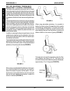
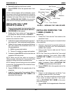
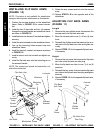
INSTALLING THE T-ARM
SOCKETS (FIGURE 2)
1. Remove the rear wheels from the wheelchair. Refer
to REMOVING/INSTALLING REAR WHEELS in
PROCEDURE 6 of this manual.
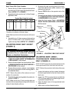
2. Position the T-arm socket and T-arm clamp on
the wheelchair frame as shown in FIGURE 2.
NOTE: The T-arm socket must be positioned on the
outside of the wheelchair frame.
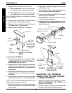
3. Install the hex screws and washers through the T-
arm clamp and T-arm socket and loosely tighten.
4. Tighten the hex screws and washers that secure
the T-arm socket to the wheelchair frame in the
following sequence:
A. Middle hex screw and washer.
B. The two (2) outside hex screws and washers.
5. Continue to repeat STEP 4 until the hex bolts are
torqued to 156-inch pounds.
NOTE: Make sure the hex bolts are torqued to
156-inch pounds, otherwise the T-arm sockets will be
capable of rotating around the wheelchair frame.
NOTE: If desired, optional locking pins can be installed
to secure the T-arm brackets to the wheelchair frame,
as shown in FIGURE 2.
6. Repeat STEPS 2-6 for the opposite side of the
wheelchair.
7. Install the T-arms into the T-arm sockets. Refer to
INSTALLING/REMOVING THE T-ARMS in this
procedure of the manual.
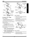
FIGURE 2 - INSTALLING THE T-ARM SOCKETS
Wheelchair Frame
Washers
T-arm Clamp
Hex Screws
T-arm Socket
Optional Locking Pins
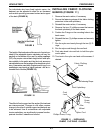
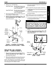
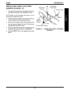
INSTALLING/REMOVING THE
T-ARMS (FIGURE 3)
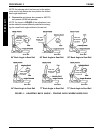
Installing
1. Position the T-arm over the T-arm socket on the
wheelchair frame.
NOTE: Make sure the locking lever is towards the front
of the wheelchair.
2. Slide the T-arm into the T-arm socket until the lock-
ing lever is in the slot in the T-arm socket and an
audible "click" is heard.
3. Pull up on the T-arm to make sure the T-arm is
locked in place.
NOTE: If the T-arm does not slide in the T-arm socket
as desired, adjust the T-arm socket. Refer to AD-
JUSTING THE T-ARMS in this procedure of the
manual.
4. Adjust the T-arm for desired height, width and
depth, if necessary. Refer to ADJUSTING THE
T-ARMS in this procedure of the manual.
5. Repeat STEPS 1-4 for the opposite side of the
wheelchair.
Removing
1. Press in on the locking lever and lift the T-arm
straight up and out of the T-arm socket.
NOTE: If the T-arm does not slide up and down in the
T-arm socket as desired, adjust the T-arm socket.
Refer to ADJUSTING THE T-ARMS in this proce-
dure of the manual.
2. Repeat STEP 1 for the opposite side of the wheel-
chair.
PROCEDURE 4 ARMS
A
R
M
S