


25
PROCEDURE 3FRAME
F
R
A
M
E
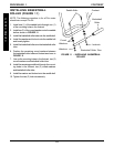
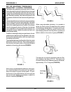
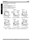
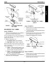
Back Canes With Push Handles
1. Remove the two (2) allen screws and locknuts that
secure the two (2) back canes to the wheelchair frame.
Refer to DETAIL "A" in FIGURE 2.
2. Reposition the back canes to one (1) of five (5) height
adjustment holes:
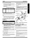
Original Back Height (in inches)
J HOLE # 10-14 12-16 14-18 16-20
1 10 12 14 16
2 11 13 15 17
3 12 14 16 18
4 13 15 17 19
5 14 16 18 20
J Holes numbered from bottom to top for reference only.
(There are no numbers on the back canes.)
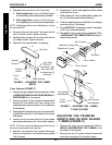
NOTE: Make sure the two (2) back canes are at the same
height.
3. Reinstall the two (2) allen screws and locknuts that
secure the back canes to the wheelchair frame.
Tighten securely. Refer to DETAIL "A" in FIGURE 2.
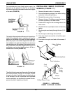
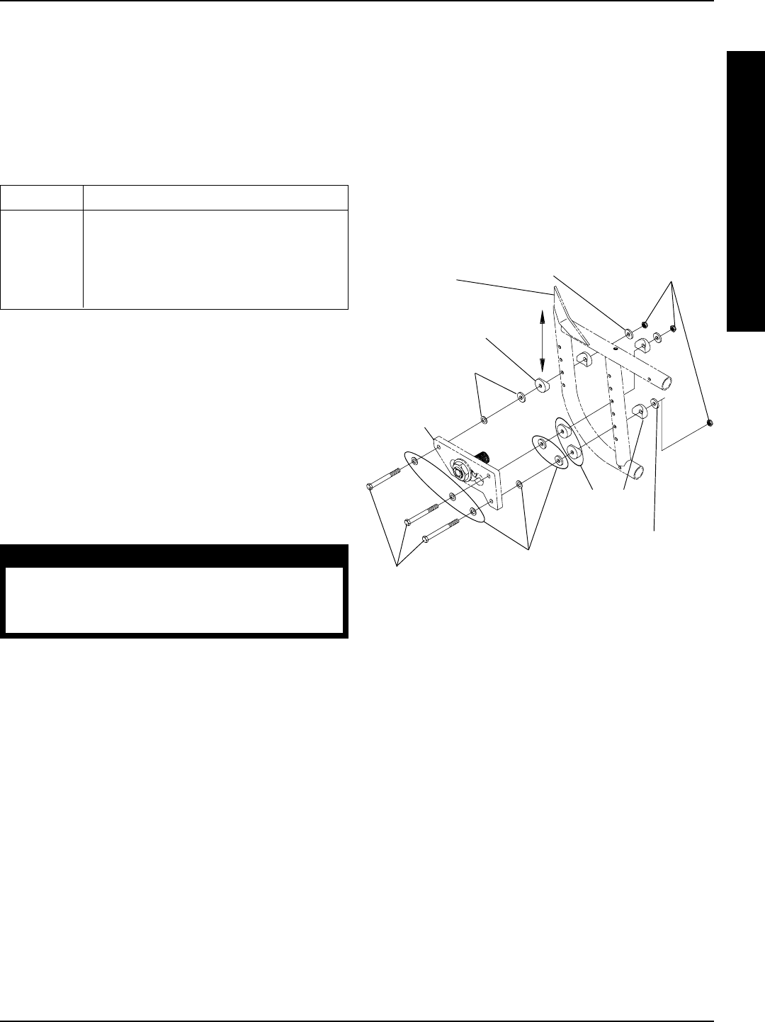
ADJUSTING REAR SEAT HEIGHT
(FIGURE 3)
WARNING
The following procedure should only be
performed by an authorized Invacare
Dealer or Qualified Technician.
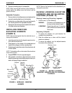
1. Determine the desired rear seat to floor height. Refer
to SEAT TO FLOOR HEIGHT DETERMINATION
in PROCEDURE 7 of this manual.
2. Remove the rear wheels from the wheelchair. Refer
to REMOVING/INSTALLING REAR WHEELS in
PROCEDURE 6 of this manual.
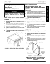
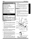
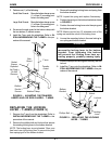
3. Remove the hex screws, washers, coved washers
and locknuts that secure the axle mounting plate to
the wheelchair frame.
NOTE: Observe the position of the washers and coved
washers for reassembly.
4. Reposition the axle mounting plate to the position de-
termined in STEP 1.
NOTE: Make sure the two (2) axle mounting plates are
mounted in the corresponding mounting holes, otherwise
a three (3) wheel situation will occur.
Washers
Coved
Washers
Coved Washer
Locknuts
Hex Screws
Wheelchair
Frame
Washers
Axle Mounting
Plate
Washer
Washer
FIGURE 3 - ADJUSTING REAR SEAT HEIGHT
5. Re-secure the axle mounting plate to the wheel-
chair frame with the hex screws, washers, coved
washers and locknuts.
6. Repeat STEPS 2-5 for the opposite side of the
wheelchair.
7. Reinstall the rear wheels onto the wheelchair. Re-
fer to REMOVING/INSTALLING REAR WHEELS
in PROCEDURE 6 of this manual.
8. Adjust the front casters. Refer to ADJUSTING
FRONT CASTER HEADTUBES in PROCEDURE
5 of this manual.
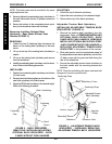
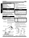
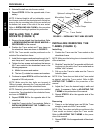
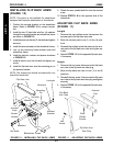
ADJUSTING BACK ANGLE -
FOLDING BACK WHEELCHAIRS
ONLY (FIGURE 4)
NOTE: DO NOT remove the hex screws that secure the
back angle bracket to the chair frame and back cane.
NOTE: Perform this procedure to both sides at the same
time.
1. Loosen the locknuts and hex screws that secure
the back angle bracket to the chair frame and the
back cane.
2. Loosen the TOP hex screw locknut and slide the
TOP hex screw away from the back angle mount-
ing bracket to adjust the cam.
3. Adjust the back canes to the approximate back
angle required.
4. Adjust cam to achieve desired position.