


36
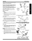
PROCEDURE 5 CASTERS
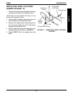
5. Retighten the two (2) hex screws and locknuts that
secure the caster headtube to the wheelchair frame.
6. Repeat STEPS 1-5 for the opposite side of the wheel-
chair.
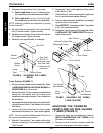
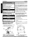
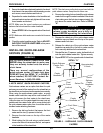
REPOSITIONING CASTER
HEADTUBES ON WHEELCHAIR
FRAME (FIGURE 5)
Mounting Caster Headtubes on the Inside of
the Wheelchair Frame
WARNING
Mounting casters on the inside of the
wheelchair frame WILL reduce the sta-
bility of the wheelchair. Try various caster
positions to find the safest caster position
for your needs.
To mount the caster headtubes on the inside of the wheel-
chair frame, reposition the right caster headtube on the
left side of the wheelchair and the left caster headtube on
the right side of the wheelchair.
Adjusting Caster Headtube Height - Pro-SA
Wheelchairs Only
Refer to CHANGING SEAT TO FLOOR HEIGHT in
PROCEDURE 7 of this manual for corresponding caster
headtube mounting position for the desired seat to floor
height.
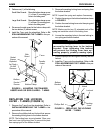
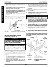
Leading/Trailing Caster Headtube
Positioning - Pro-SA Wheelchairs Only
LEADING. Mount the casters on the wheelchair frame
with the caster headtube towards the front of the wheel-
chair to Lengthen the Wheelbase.
TRAILING. Mount the casters on the wheelchair frame
with the caster headtube towards the rear of the wheel-
chair to Shorten the Wheelbase.
NOTE: The wheelchair is shipped from the factory with
the caster headtube in the LEADING position.
Adjusting Turning Radius - ALL Pro Series
Wheelchairs EXCEPT Pro-SA
WARNING
Mounting casters towards the rear of the
wheelchair frame WILL reduce the sta-
bility of the wheelchair. Try various caster
positions to find the safest caster position
for your needs.
9. Repeat STEPS 1-8 for the opposite side of the wheel-
chair.
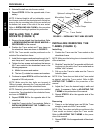
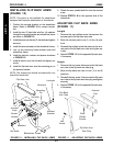
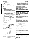
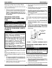
NOTE: As shown in FIGURE 3, the adjustment cam can
be rotated to several different positions thus changing the
overall caster headtube angle relative to the seat frame
angle.
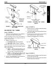
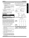
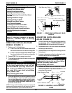
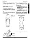
ALL Pro Series Wheelchairs EXCEPT Pro-SA
(FIGURE 4)
1. Place the wheelchair on a flat surface.
2. Loosen, but do not remove the two (2) locknuts and
hex screws that secure the caster headtube to the
wheelchair frame.
3. Position a large right triangle or "L" square on the flat
surface and against the caster headtube.
4. Using two (2) wrenches, adjust the caster headtube
by turning CLOCKWISE or COUNTERCLOCK-
WISE until the caster headtube is parallel and square
to the large right triangle or "L" square.
C
A
S
T
E
R
S
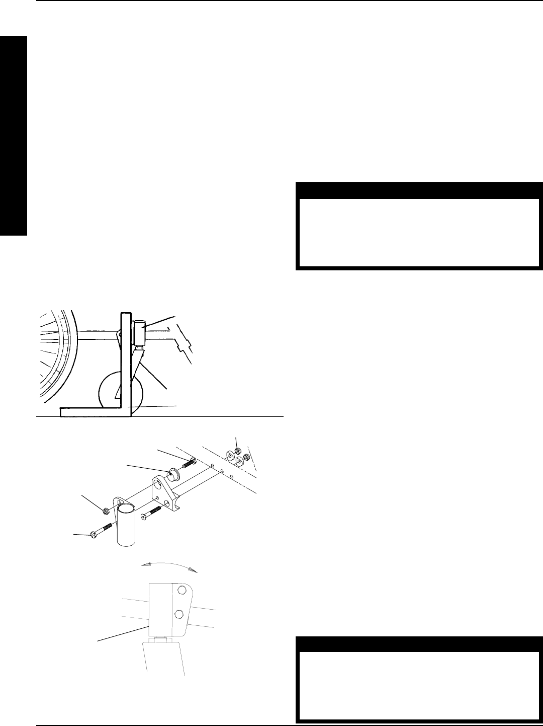
FIGURE 4 - ADJUSTING FRONT CASTER
HEADTUBES - ALL PRO SERIES WHEELCHAIRS
EXCEPT PRO-SA
Adjustment Cam
Hex Screw
Hex
Screw
Locknut
Caster Headtube
Caster/Fork
"L" Square
Locknut
NOTE: Exploded for clarity,
DO NOT disassemble.
Caster
Headtube