


45
Replacing the High/Undermount Wheel Lock
1. Remove the socket cap screws and remove the
existing wheel lock from the wheelchair.
2. Install the new wheel lock and secure with the ex-
isting socket cap screws.
3. Adjust the high/undermount wheel lock Refer to
the following procedure.
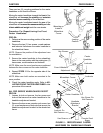
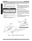
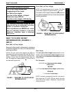
Adjusting the High/Undermount Wheel
Lock
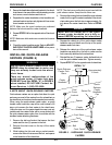
1. Engage the wheel locks.
NOTE: Any wheel lock adjustment should embed the
wheel lock shoe at least 3/16-inch into the pneumatic
tire (1/8-inch for urethane wheels) when engaged.
2. If necessary, loosen the socket cap screw(s) that
secure the High/Undermount wheel locks to the
wheelchair frame and adjust position of the wheel
lock until the 3/16-inch (1/8-inch for urethane
wheels) measurement is obtained for correct
wheel lock adjustment.
3. Securely tighten the socket capscrew(s).
4. Engage the wheel locks and push against the
wheelchair and determine if the wheel locks en-
gage the wheel locks enough to hold the wheel-
chair.
5. Repeat the above procedures until the wheel locks
hold the wheelchair.
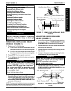
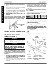
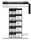
WHEEL LOCK EXTENSION
HANDLE INSTALLATION
(FIGURE 12)
NOTE: Wheel lock extension handles may be installed
on all HIGH mount wheel locks (push or pull type) NOT
already equipped with swing-up extension handles.
1. Remove the plastic cover on the existing wheel
lock handle, if necessary.
2. Remove the button screw, washer and locknut that
secure the existing wheel lock handle and spacer
to the wheel lock assembly.
3. Attach the looped end of the elastic cord of the
wheel lock extension handle over the spacer of
the existing wheel lock handle.
4. Reattach the existing wheel lock handle and spacer
onto the wheel lock assembly and secure with the
button screw, washer and locknut.
NOTE: The elastic cord is made of stretchable mate-
rial and may be adjusted to a tight or loose fit to meet
the need of the user.
5. Remove the black tip of the wheel lock extension
handle.
6. Push the opposite end of the elastic cord up and
through the slotted hole in the wheel lock exten-
sion handle.
7. Run the elastic cord through the washer and tie a
knot in the elastic cord above the washer.
8. Pull the elastic cord back down into the wheel lock
extension handle.
9. Reinstall the black tip onto the wheel lock exten-
sion handle.
10. Slide the wheel lock extension handle over the ex-
isting wheel lock handle.
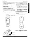
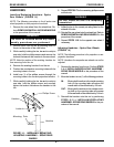
Button
Screw
Spacer
Elastic
Cord
Knot
Washer
Black
Tip
Wheel Lock
Extension
Handle
Existing
Wheel Lock
Handle
Locknut
Wheel
Lock
FIGURE 12 - WHEEL LOCK EXTENSION
HANDLE INSTALLATION
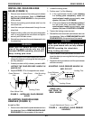
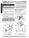
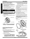
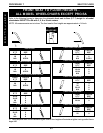
INSTALLING/ADJUSTING THE
ANTI-TIPPERS (FIGURE 13)
Installing the Anti-tippers
1. Position the two (2) half clamps of the anti-tipper
on the wheelchair frame. Make sure they sit flush
against each other.
2. Install the top hex screw and loosely tighten with
locknut.
R
E
A
R
W
H
E
E
L
S
REAR WHEELS PROCEDURE 6
Washer
Loop