


30
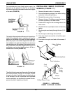
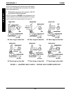
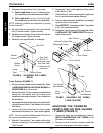
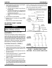
3. Reposition the arm tube on the T-arm post:
A. Desk Length Arms - to one (1) of three (3) posi-
tions depending on the desired arm pad depth.
B. Full Length Arms - to one (1) of five (5) posi-
tions depending on the desired arm pad depth.
NOTE: Additional positions are obtainable by turning
the arm tube 180
o
.
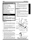
4. Re-secure the arm tube to the T-arm post with the
two (2) socket screws. Tighten securely.
5. Reattach the arm pad to the arm tube with the two
(2) phillips screws. Tighten securely.
6. Repeat for the opposite side, if necessary.
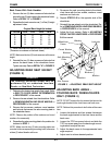
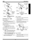
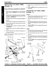
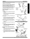
6. Squeeze the T-arm socket together until the socket
is flush with the T-arm.
7. While holding the T-arm socket together, tighten the
four (4) hex screws and washers securely.
8. Press in on the locking lever and lift the T-arm straight
up and out of the T-arm socket.
9. Repeat STEPS 5-7, if necessary until the T-arm slides
in the T-arm socket as desired.
10. Reinstall the T-arm socket onto the wheelchair. Refer
to INSTALLING THE T-ARM SOCKETS in this pro-
cedure of the manual.
Socket
Screws
Arm Pad
Phillips
Screw
T-arm
Post
Arm Tube
NOTE: If
necessary, turn
arm tube 180
o
to obtain two (2)
positions.
Phillips Screw
FIGURE 6 - ADJUSTING THE T-ARMS -
DEPTH
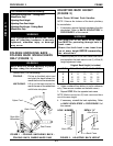
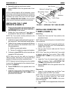
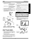
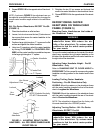
T-arm Sockets (FIGURE 7)
1. Remove the rear wheels from the wheelchair. Refer
to REMOVING/INSTALLING REAR WHEELS in
PROCEDURE 6 of this manual.
2. Remove the three (3) hex screws and washers that
secure the T-arm socket and T-arm clamp to the
wheelchair frame and remove the T-arm socket from
the wheelchair.
3. If equipped with optional locking pins, remove the lock-
ing pins that secure the T-arm socket to the wheel-
chair frame.
4. Loosen, but do not remove the four (4) hex screws
and washers that secure the T-arm socket together.
NOTE: The T-arm socket will disassemble if the four (4)
hex screws and washers are removed.
5. Slide the T-arm into the T-arm socket until the lock
lever is in the slot in the T-arm socket and an audible
"click" is heard.
Washers
Wheelchair Frame
Hex Screws
T-arm Clamp
T-arm Socket
Optional Locking Pins
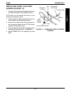
ADJUSTING THE TRANSFER
ASSISTS AND/OR SIDE GUARDS
- T-ARMS (FIGURE 8)
1. Remove the T-arm from the wheelchair. Refer to
INSTALLING/REMOVING THE T-ARMS in this
procedure of the manual.
2. Remove the two (2) bottom socket screws that
secure the side guard to the bottom clamp.
FIGURE 7 - ADJUSTING THE T-ARMS -
T-ARM SOCKETS
PROCEDURE 4 ARMS
A
R
M
S
Hex Screws
and Washers
T-arm
Socket
Hex Screws
and Washers
T-arm