


38
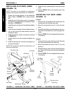
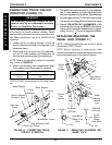
3. Secure the headtube adjustment bracket to the wheel-
chair frame in the new position with the existing counter
sunk screw, coved washers and locknut.
4. Reposition the caster headtube on the headtube ad-
justment bracket and securely tighten with hex screw,
coved washer and locknut.
NOTE: Make sure the coved washers are positioned
between the locknuts and the caster headtube.
5. Repeat STEPS 1-4 for the opposite side of the wheel-
chair.
NOTE: Make sure both casters are mounted in the same
position.
6. Check the caster headtube angle. Refer to ADJUST-
ING FRONT CASTER HEADTUBES in this proce-
dure of the manual.
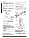
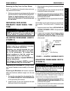
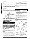
INSTALLING QUICK-RELEASE
CASTERS (FIGURE 6)
WARNING
Pull on quick-release casters each time
BEFORE using the wheelchair to make sure
they are securely locked onto the wheel-
chair frame.
There are several configurations of the
quick-release caster. If caster fork stem
DOES NOT look like DETAIL "A" in FIGURE 6
when installed, DO NOT USE. Contact Ac-
count Services, 1-(800)-333-6900.
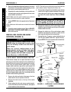
A NOTE ABOUT QUICK-RELEASE CASTERS
Quick-release casters are an option that allow for quick
and easy removal of the casters from the wheelchair so
the wheelchair can be stored and transported conveniently.
When using the quick-release caster option, a spring
loaded caster head tube cap will be used instead of a
stem nut to secure the front caster to the chair frame.
Unlike the stem nut, the caster head tube cap is not ad-
justable and thus caster flutter will be more evident with
the quick-release caster option than it would be with the
standard caster attaching hardware.
1. Remove the bolt and locknut that secure the front
caster and the two (2) spacers to the fork.
2. Remove the dust cover on the top of the caster
headtube.
3. While holding the fork and using a socket wrench,
remove the locknut that secures the fork, and spacer
in the headtube of the wheelchair.
C
A
S
T
E
R
S
PROCEDURE 5 CASTERS
NOTE: The dust cover and locknut are not used with the
quick release casters. Keep them for future use.
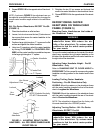
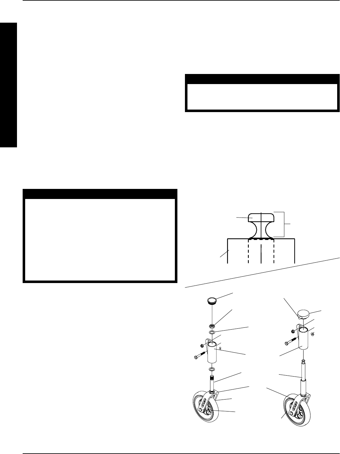
4. Remove the existing fork and install the quick release
caster fork through the caster headtube of the wheel-
chair making sure the fork stem is approximately 1/4-
inch above the caster head tube. Refer to DETAIL
"A".
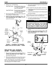
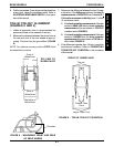
WARNING
Make sure the detent pin of the quick-
release caster headtube cap is fully re-
leased BEFORE operating the wheelchair.
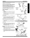
5. Depress the detent pin of the quick-release caster
headtube cap and install over the top of the quick-
release caster fork stem.
6. Release the detent pin of the quick-release caster
headtube cap and pull on the fork to make sure the
fork is securely attached to the wheelchair.
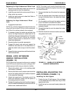
7. Reinstall the two (2) spacers, caster, bolt and locknut
onto the quick-release caster fork. Tighten securely.
8. Repeat STEP 1-7 for the opposite side of wheelchair.
Bolt
Dust
Cover
Locknut
Detent Pin
Quick-
Release
Caster
Headtube
Cap
Fork
Fork Stem
FIGURE 6 - INSTALLING QUICK-RELEASE
CASTERS
Spacer
Approximately
1/4-inch
Quick-Release
Caster Fork
Stem
Caster
Headtube
DETAIL "A"
Caster
Headtube
Front Caster
Locknut