


26
FRAMEPROCEDURE 3
F
R
A
M
E
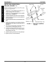
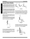
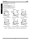
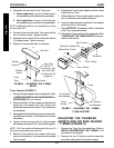
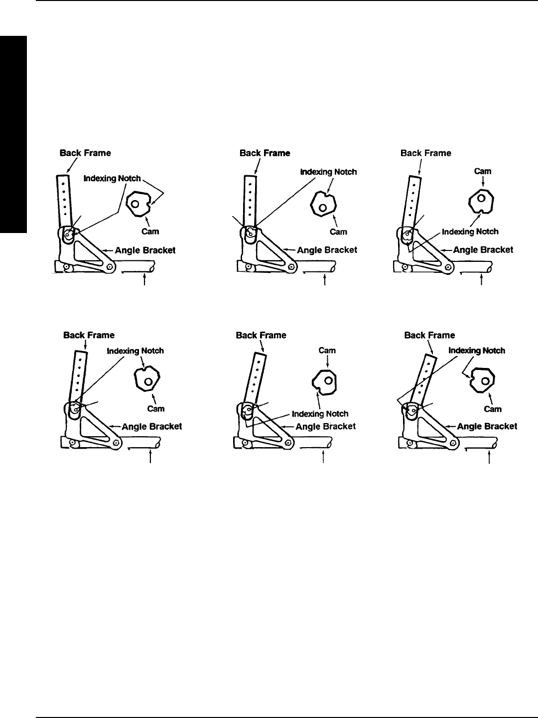
NOTE: An indexing notch has been put on the adjust-
ment cam to help determine cam position for desired
back angle adjustment.
5. Reassemble and torque hex screws to 480-720
inch pounds (40-60 foot pounds).
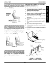
NOTE: As shown in FIGURE 4, the adjustment cam
can be rotated to several different positions thus chang-
ing the overall back angle relative to the seat rail.
73
o
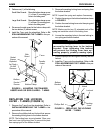
Back Angle to Seat Rail77
o
Back Angle to Seat Rail84
o
Back Angle to Seat Rail
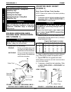
FIGURE 4 - ADJUSTING BACK ANGLE - FOLDING BACK WHEELCHAIRS ONLY
Seat Rail
Seat RailSeat Rail
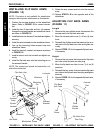
94
o
Back Angle to Seat Rail 85
o
Back Angle to Seat Rail90
o
Back Angle to Seat Rail
Seat Rail Seat Rail Seat Rail
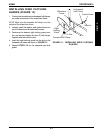
TOP Hex
Screw and
Locknut
TOP Hex
Screw and
Locknut
TOP Hex
Screw and
Locknut
TOP Hex
Screw and
Locknut
TOP Hex
Screw and
Locknut
TOP Hex
Screw and
Locknut