


35
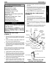
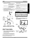
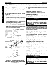
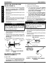
8. To properly tighten front caster forks and guard against
flutter, perform the following check:
a. Tip back of wheelchair to floor.
b. Pivot both forks and casters to top of their arc
simultaneously.
c. Let casters drop to bottom of arc (wheels should
swing once to one-side, then immediately rest in
a straight downward position).
d. Adjust locknuts according to freedom of caster
swing.
9. Test wheelchair for maneuverability.
10. Readjust locknuts if necessary and repeat STEPS
8-9 until correct.
11. Snap dust cover over the locknut and stem.
ADJUSTING FRONT CASTER
HEADTUBES
WARNING
The following procedure should be per-
formed only by an authorized Invacare
Dealer or Qualified Technician.
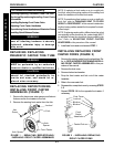
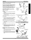
A NOTE ABOUT CASTER HEADTUBE
ADJUSTMENTS
Whenever the seat height is raised or lowered by chang-
ing the caster size, fork stem length, rear wheel size or
axle mounting plate adjustments, the caster angle needs
to be checked to maintain a 90
o
angle between the caster
headtube and the ground/floor. Caster headtubes that are
perpendicular to the floor will roll better, track straighter
and minimize any "3-wheeling" of the wheelchair.
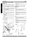
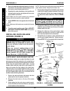
Pro-SA Model Wheelchairs (FIGURE 3)
1. Place the wheelchair on a flat surface.
2. Loosen, but do not remove, the two (2) hex screws
and locknuts that secure the caster headtube to the
wheelchair frame.
3. Remove the TOP locknut and adjustment cam from
the caster headtube.
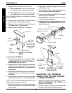
4. Position a large right triangle or "L" square on the flat
surface and against the caster headtube.
5. Position the caster headtube flat against the right tri-
angle or "L" square.
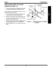
6. Reinstall adjustment cam onto the top hex screw.
7. With the caster headtube flat against the right triangle
or "L" square, rotate and position the adjustment cam
until the adjustment cam sits flush in the grooves of
the caster headtube.
NOTE: An indexing notch has been put on the adjust-
ment cam to help determine the adjustment cam po-
sition for the opposite caster headtube.
8. Reinstall the locknut onto the top hex screw and se-
curely tighten the two (2) hex screws and locknuts.
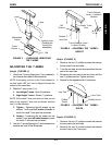
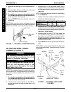
FIGURE 3 - ADJUSTING FRONT CASTER
HEADTUBES - PRO-SA MODEL WHEELCHAIRS
Wheelchair Frame
Adjustment Cam
Caster Headtube
Indexing Notch
Caster
Headtube
Perpendicular
to Floor
Caster
Headtube
Caster/Fork
"L" Square
C
A
S
T
E
R
S
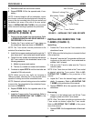
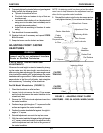
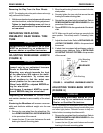
PROCEDURE 5CASTERS
CASTER
TRAILING
CASTER
LEADING
Indexing Notch
Floor
Flat Surface
Hex Screws
and Locknuts