


Instruction Manual
IM-106-880C, OI
September 2009
5-15
Hazardous Area OCX 8800
COe D/A trim procedure using HART
Use the following procedure to perform the COe D/A trim procedure using the
Field Communicator. If necessary, refer to Section 6, Field Communicator,
Field Communicator, for the HART menu tree.
NOTE
To select a menu item, either use the up and down arrow keys to scroll to the
menu item and press the right arrow key or use the number keypad to select
the menu item number.
To return to a preceding menu, press the left arrow key.
1. From the DIAG/SERVICE menu, select D/A TRIM. Press the up or
down arrow to select COe D/A Trim.
2. Press the right arrow key to start the procedure. (If you wish to exit D/A
Trim with no changes, select ABORT.)
3. The Field Communicator displays WARNING: Loop should be
removed from automatic control. Remove the Hazardous Area OCX
8800 from any automatic control loops to avoid a potentially dangerous
operating condition and press OK.
4. The Field Communicator displays Connect reference meter to
Combustibles output.
5. Remove the electronics housing cover.
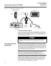
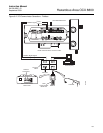
6. Refer to Figure 2-6. Connect a digital multimeter to read the milliamp
output from the COe D/A converter circuit. Connect the positive lead to
the AOUT2+ terminal and connect the negative lead to the AOUT2-
terminal. Then, press OK at the HART communicator.
7. The Field Communicator displays Setting Fld dev output to 4 mA.
Press OK. Read the COe
millamp output at the digital multimeter. Enter
the reading at the Field Communicator and press ENTER. (Select
ABORT to exit without changes).
8. The Field Communicator displays Setting Fld dev output to 20 mA.
Press OK. Read the COe
millamp output at the digital multimeter. Enter
the reading at the Field Communicator and press ENTER. (Select
ABORT to exit without changes).
9. The Field Communicator displays Setting Fld dev output to 4 mA.
Press OK.
10. The Field Communicator displays Fld dev output 4.00 mA equal to
reference meter? Using the up or down arrow, select 1 Yes or 2 No
and Press ENTER. If No, the process repeats from step 6.
11. The Field Communicator displays Setting Fld dev output to 20 mA.
Press OK.
12. The Field Communicator displays Fld dev output 20.00 mA equal to
reference meter? Using the up or down arrow, select 1 Yes or 2 No
and Press ENTER. If No, the process repeats from step 7.
13. The Field Communicator displays NOTE: Loop may be returned to
automatic control.