


Instruction Manual
IM-106-880C, OI
September 2009
Hazardous Area OCX 8800
1-6
System Operation
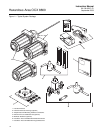
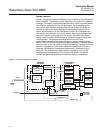
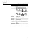
Figure 1-2 shows the relationship between the components of the Hazardous
Area OCX 8800. The sensors and the electronics are contained in separate
housings. The sensor housing and probe mounts to a duct or process wall so
that the probe protrudes into the flue gas stream. An air powered eductor
continuously pulls samples of the process flue gas through the probe to a
chamber in front of the sensor housing where the sample passes the O
2
sensor and continues on to the COe sensor. Dilution air is provided to the
COe sensor and reference air to the O
2
sensor. After the gas sample flows
past the O
2
sensor and through the COe sensor, it is drawn through the
eductor where it mixes with the eductor air and exits through exhaust back
into the system. The electronics housing contains the CPU and
communication boards which convert the sensor inputs into digital output
signals. The CPU can also initiate and perform calibrations. Three test gasses
and instrument air can be turned on and off by solenoids. Test gas flow to the
sensors is regulated by a flow meter between the electronics and sensor
housings. Instrument air is separated into eductor air, reference air, and
dilution air. The instrument air solenoid does not allow air flow until the
heaters are up to temperature. This minimizes the amount of sampled
process flue gas being pulled into cold sensors causing condensation.
Figure 1-2. System Operation Diagram
Low O
Test Gas
2
COe
Combustibles
Sensor
O
Sensor
2
Eductor
Probe
Exhaust
CPU
COMM
Board
Optional
Test Gas
Solenoids
Instrument Air
Solenoid
High O
Test Gas
2
CO
Test Gas
Instrument
Air
Dilution Air
Reference Air
Eductor Air
Flow Meter
50 cc/min.
(0.1 scfh)
SENSOR
HOUSING
ELECTRONICS
HOUSING
Flow Meter
7 scfh
39690001
Sample
Gas
Power
Supply