


Instruction Manual
IM-106-880C, OI
September 2009
Hazardous Area OCX 8800
Index-2
M
Manual Calibration,
Fieldbus . . . . . . . . . . . . 5-8, 5-10
Manual Calibration, HART . . . . 5-5
Manual Calibration, LOI . . . . . . 5-4
Mapping of PWA . . . . . . . . . . . . 7-7
Material Safety Data Sheet . . .A-24
Menu Tree
Fieldbus . . . . . . . . . . . . . . . 6-9
HART . . . . . . . . . . . . . . . . . 6-5
LOI . . . . . . . . . . . . . . . . . . . 4-4
N
Nernst Equation . . . . . . . . . . . . 1-3
Network Communication,
Fieldbus . . . . . . . . . . . . . . . . . 7-4
O
O2 Cell and Heater Strut 9-26, 9-28
O2 Cell and Heater Strut
Assembly . . . . . . 9-11, 9-18, 10-9
O2 Cell Output Voltage . . . . . . . 1-5
O2 Cell Replacement Kit . . . . . 9-18
O2 Cell, Heater, and
Thermocouple . . . . . . . . . . . 9-18
O2 Cell, Thermocouple,
& Heater Connections 9-12, 9-27
OCX Implemented
Function Blocks . . . . . . . . . . . 7-6
OCX Removal and Installation . 9-1
OCX Specifications . . . . . . . . . 1-12
OCX with Integral Electronics . . 9-2
Off-Line and On-Line
Operations . . . . . . . . . . . . . . . 6-4
Operating Mode Enumerations 7-18
Operation Diagram . . . . . . . . . . 1-6
Oxygen and Cell Output . . . . . . 8-7
P
Personal Computer (PC) . . . . . . 1-5
PID Function Block
Alarm Detection . . . . . . . . 7-43
Application Information . . 7-44
Modes . . . . . . . . . . . . . . . 7-42
Parameters . . . . . . . . . . . 7-36
Troubleshooting . . . . . . . . 7-50
PlantWeb Alerts . . . . . . . . . . . . . 7-6
Power Up . . . . . . . . . . . . . . . . . 3-5
Pre-Heater . . . . . . . . . . . . . . . . 9-20
Pre-Heater Alignment . . . . . . .9-21
Product Matrix . . . . . . . . . . . . .1-14
PWA Simulate . . . . . . . . . . . . . 7-10
R
Reference Air Tube . . . . . . . . . 9-11
Remove Eductor . . . . . . . . . . .9-16
Remove EEprom . . . . . . . . . . .9-29
Remove Electronics Stack . . . 9-30
Remove Flash PROM . . . . . . . 9-29
Remove LOI Module
and Board . . . . . . . . . . . . . . .9-29
Remove OCX 8800
with Integral Electronics . . . . . 9-2
Remove OCX
with Remote Electronics . . . . . 9-5
Remove Remote Electronics . . . 9-7
Remove Solenoid Valves . . . . 9-31
Remove Tube Fittings . . . . . . . 9-35
Repair Sensor Housing . . . . . . 9-10
Replace Tube Fittings . . . . . . . 9-35
Reset Procedure . . . . . . . . . . . 3-14
Resistance Devices (RTD) . . . . 1-4
Resource Block . . . . . . . . . . . . . 7-6
Resource Blocks . . . . . . . . . . . .7-4
Returning Material . . . . . . . . . . .C-1
RTD . . . . . . . . . . . . . . . . . . . . . .1-4
S
Samole Tube Support . . . . . . . 1-10
Sample and Exhaust
Tubes . . . . . . . . . . . . . 9-17, 9-21
Sample Block
Heater Rods . . . . . . . . 9-12, 9-27
Selected Distributed
Control Systems . . . . . . . . . . . 1-5
Sensor Housing Components .10-2
Sensor Housing Disassembly . 9-10
Sensor Housing Enumerations 7-19
Sensor Housing Leak Test . . . 9-28
Sensor Housing Terminals . . . . 9-6
Sensor Housing Type . . . . . . .7-19
Signal Conversion . . . . . . . . . . 7-26
Simulation . . . . . . . . . . . . . . . . 7-25
Single Link Fieldbus Network . .7-5
Solenoid Power Terminals . . . .9-34
SPA Configuration Menu . . . . . B-6
SPA Front Panel . . . . . . . . . . . B-4
SPA Interface Connections . . . B-2
SPA Setup for Calibration . . . . B-3
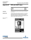
SPA with HART Alarm . . . . . . . B-1
Specifications . . . . . . . . . . . . . .1-12
Status Handling . . . . . . . . . . . .7-29
Support Resource Block Errors 7-12
System Configuration . . . . . . . .1-4
System Description . . . . . . . . . .1-3
System Features . . . . . . . . . . . .1-5
System Operation . . . . . . . . . . .1-6
System Package . . . . . . . . . . . .1-2
T
Terminals Insulator . . . . . . . . .9-28
Test Gas Values . . . . . . . . . . . . .3-5
Total Power Loss . . . . . . . . . . . .8-2
Transducer Block
Channel Status . . . . . . . . . . .7-22
Transducer Block
Enumerations . . . . . . . . . . . .7-17
Transducer Block Errors . . . . .7-22
Transducer Block Parameters .7-13
Transducer Block Simulate . . .7-22
Transducer Blocks . . . . . . . . . . .7-4
Typical System Installation . . . .1-9
Typical System Package . . . . . .1-2
W
Warranty Service . . . . . . . . . . . C-1