


Instruction Manual
IM-106-880C, OI
September 2009
9-25
Hazardous Area OCX 8800
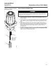
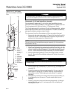
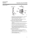
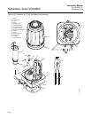
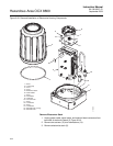
8. Install and fasten thermocouple (8, Figure 9-17).
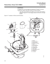
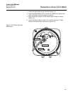
9. Position band heater as shown in Figure 9-19 and Figure 9-20 and
tighten band heater clamp screw. The heater insulator (9) end joint must
line up with the band gap of the COe band heater (10).
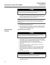
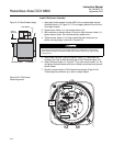
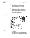
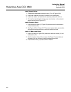
10. Reconnect the COe sensor, thermocouple, and heater wires at the
sensor housing terminal blocks. Refer to Figure 9-21.
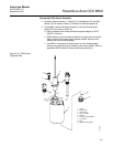
11. Install and fasten the COe insulator (1, Figure 9-17) around COe sensor
assembly (5). All wiring must remain outside of the insulator.
12. If terminal block mounting (13, Figure 9-17) was moved, reinstall with
two base mounting screws.
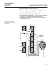
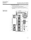
Figure 9-21. COe Sensor,
Thermocouple, and Heater
Connections
O2
RED
T/C O2
T/C CO
T/C SB
EXC
CJC
COe Sensor Wires
COe Heater Wires
COe Sensor
Assembly
CO REF
CO ACT
Sensor HousingTerminals
+
-
HTR 02
HTR SB
2
2
1
+
-
+
-
+
-
+
-
+
-
+
YEL
-
+
37390018
HTR 02
2
1
HTR CO
1
WHT
BLU
RED
RED
WHT
COeThermocouple Wires
-
EXC
RED
BLU
CJC Sensor
NOTE: All wires
at these terminals
are in the CJC
current loop.