


Instruction Manual
IM-106-880C, OI
September 2009
Hazardous Area OCX 8800
8-6
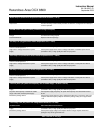
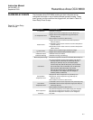
ADC Failure (Voltage to digital conversion could not complete)
ADC Ref Error (Voltage to digital conversion not accurate)
Probable Cause Recommended Corrective Action
Incorrect wiring between electronics and sensor
housings
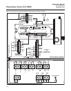
Check all wiring between the electronics and sensor housings per Figure 8-3. Correct
wiring faults.
Electronics package failure Replace electronics package.
O2 Htr Failure (Oxygen sensor heater could not reach final temperature)
Probable Cause Recommended Corrective Action
O
2
heater circuit wiring open Check O
2
cell heater circuit for broken wire or loose connection per Figure 8-3 and
Figure 9-8. Repair broken wire or loose connection.
O
2
heater open Check resistance of O
2
heater per Figure 9-8. Normal O
2
heater resistance is 62.5
Ohms. Replace O
2
heater if heater is open or has a large resistance.
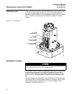
Heater electronics failure Check heater fuse F3 in electronics housing per Figure 8-1. If open, locate and correct
cause of overload. If F3 is not open, or if cause of overload cannot be found, replace
electronics package.
COe Htr Failure (Combustibles sensor heater could not reach final temperature)
Probable Cause Recommended Corrective Action
COe heater circuit wiring open Check COe heater circuit for broken wire or loose connection per Figure 8-3 and
Figure 9-9. Repair broken wire or loose connection.
COe heater open Check resistance of COe heater per Figure 9-9. Normal COe heater resistance is 97.7
Ohms. Replace COe heater if heater is open or has a large resistance.
Heater electronics failure Check heater fuse F3 in electronics housing per Figure 8-1. If open, locate and correct
cause of overload. If F3 is not open, or if cause of overload cannot be found, replace
electronics package.
SB Htr Failure (Sample block heater could not reach final temperature)
Probable Cause Recommended Corrective Action
Sample block heater circuit wiring open Check sample block heater circuit for broken wire or loose connection per Figure 8-3
and Figure 9-8. Repair broken wire or loose connection.
Sample block heater open Check resistance of sample block heater per Figure 9-8. Normal sample block heater
resistance is 36.4 Ohms each (18.2 Ohms with both heaters in parallel). Replace
sample block heater if heater is open or has a large resistance.
Heater electronics failure Check heater fuse F4 in electronics housing per Figure 8-1. If open, locate and correct
cause of overload. If F4 is not open, or if cause of overload cannot be found, replace
electronics package.
Sensor housing exposed to high wind and/or
extreme cold temperatures
If above probable causes are not causing the SB heater failure, install flange insulator
(PN 6P00162H01).
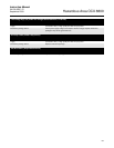
Cal Warning (Calibration warning)
Cal Failed (Calibration failed)
Probable Cause Recommended Corrective Action
Calibration gas supply low or gas connection
leaking
Check calibration gas supplies and connections. Adjust gas pressure and flow.
Replenish low calibration gas supplies and tighten or repair loose or leaking
connections. When calibration gas supplies are adequate, recalibrate.
O
2
cell degraded or failed:
O2 Slope Error (Slope <34.5 mV/Dec or >57.5
mV/Dec)
O2 Constant Error (Constant not between -20
mV to +20 mV)
Check O
2
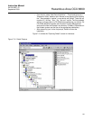
cell impedance by reading the O2 Cell Imped value via the LOI (see
Figure 4-4, sheet 2), or the O2 Snsr R value via FOUNDATION fieldbus menu tree (see
Figure 6-7, sheet 2). If cell impedance is zero, replace O
2
cell. If cell impedance is less
than 5000 ohms, check for cell housing ground fault. Repair ground fault. If cell
impedance is greater than 5000 ohms and no ground fault is indicated, replace O
2
cell.
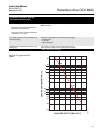
Flow calibration gas to the O
2
cell. Read the cell millivolt output. Plot the cell millivolt
output and the calibration gas O
2
concentration on the chart shown in Figure 8-2. If the
plotted values do not fall on the slope line shown in Figure 8-2, replace the O
2
cell.
Table continued on next page