


Instruction Manual
IM-106-880C, OI
September 2009
Hazardous Area OCX 8800
9-10
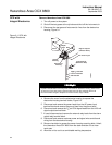
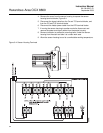
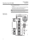
Install Remote Electronics Housing
1. Mount remote electronics housing on wall or pipe within distance of
signal and heater cables in use.
2. Remove the electronics housing cover.
3. If removed, install the power and signal cables and the customer power
and signal conduits and wiring at the electronics housing.
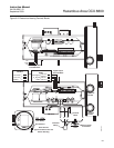
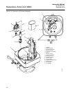
4. Connect the signal cable leads to the O
2
cell and thermocouple
connector (J4), and to the COe and CJC connector (J5), Figure 9-6.
5. Connect the heater cable leads to the heater power connector (J3).
6. Connect the line (L1 wire) to the L1 terminal, and the neutral (N wire) to
the N terminal on the AC power input terminal block, Figure 9-6.
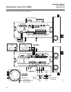
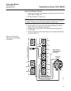
7. Connect the ground lead to the ground stud. Secure the connection with
two nuts. Attach a separate ground lead (G wire) from the ground stud
to the G terminal on the power input terminal block.
8. If used, connect external relay leads to the alarm output relay terminal.
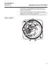
9. Connect the test gas and instrument air lines to the remote electronics
housing. Connect the calibration gas line and instrument air line to the
remote electronics housing.
10. Refer to Figure 9-3 and Figure 9-6. Make sure all test gas lines and
electrical connections are complete.
11. Install the cover on the electronics housing.
12. Turn on the test gasses at the cylinders and open the instrument air
valve.
13. Restore power to the system.
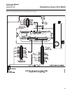
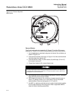
REPAIR SENSOR
HOUSING
Use the following procedures to remove damaged components from the
Hazardous Area OCX 8800 sensor housing and to install new replacement
parts. Disassemble the unit only as needed to replace damaged components.
Use the assembly procedures that apply to install replacement parts and
reassemble the unit.
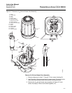
Sensor Housing
Disassembly
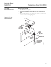
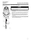
Remove Cover and Terminals Insulator
1. Loosen screw (1, Figure 9-7) and slide locking clip (2) away from cover.
Retighten screw (1).
2. With two hands or strap wrench, turn cover (3) counterclockwise to
loosen. Unthread and remove cover.
3. Inspect cover o-ring (4) for wear or damage. Replace cover o-ring if
damaged.
4. Unsnap terminal marking plates (5) and remove terminal insulator (6).