


Instruction Manual
IM-106-880C, OI
September 2009
3-3
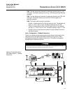
Hazardous Area OCX 8800
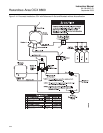
SW1 The two settings are internally or externally powering the O
2
4-20
mA signal. The factory setting is for the O
2
4-20 mA signal to be internally
powered.
SW2 The two settings are internally or externally powering the COe 4-20
mA signal. The factory setting is for the COe 4-20 mA signal to be
internally powered.
SW3 The factory sets this switch as follows:
• Position 1 determines the O
2
4-20 mA signal rail limit. The settings are
high, 21.1 mA, or low, 3.5 mA. The factory setting is low, 3.5 mA.
• Position 2 determines the COe 4-20 mA signal rail limit. The settings
are high, 21.1 mA, or low, 3.5 mA. The factory setting is high, 21.1 mA.
• Positions 3 and 4 must be set as shown for proper software control of
the device heaters.
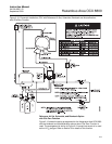
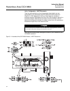
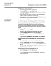
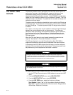
Verify Configuration - Fieldbus Electronics
There is one switch on the microprocessor board which must be set for the
Hazardous Area OCX 8800 with fieldbus electronics (Figure 3-2). SW3
configures the sample line heater control circuit. This switch is accessible
through holes in the electronics box.
Figure 3-2. Hazardous Area
OCX 8800 Defaults - Fieldbus
Electronics
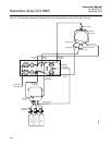
Remove power from the Hazardous Area OCX 8800 before changing defaults. If defaults
are changed under power, damage to the electronics may occur.