


Instruction Manual
IM-106-880C, OI
September 2009
7-13
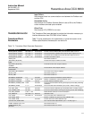
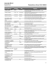
Hazardous Area OCX 8800
Input Failure
Set whenever there is a communication error between the Fieldbus card
and the OCX.
Simulation Active
Set whenever the Fieldbus Simulate Switch is set to ON at the Fieldbus
card or software simulate option enabled.
Other Error
Set whenever XD_ERROR is non-zero.
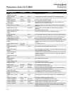
TRANSDUCER BLOCK The Transducer Block was designed to provide the information necessary to
interface Hazardous Area OCX 8800 to the Fieldbus.
Transducer Block
Parameters
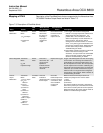
Table 7-3 gives a description of all parameters, or gives the location of the
Fieldbus specifications the description can be found.
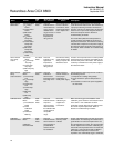
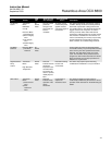
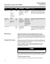
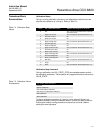
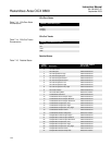
Table 7-3. Transducer Block Parameter Description
Parameter Mnemonic Valid Range Units Description
ALARM_RELAY_EVENT1 See Table 7-7 Enumerated The first of three conditions that cause the alarm output to turn on..
ALARM_RELAY_EVENT2 See Table 7-7 Enumerated The second of three conditions that cause the alarm output to turn on.
ALARM_RELAY_EVENT3 See Table 7-7 Enumerated The third of three conditions that cause the alarm output to turn on.
ALARM_RELAY_STATE 0: Off – 1: On Enumerated The state of the alarm output.
ALERT_KEY See FF-891 section 5.3.
ANALYZER_SW_BUILD_
DATE
The date the analyzer software was built.
ANALYZER_SW_BUILD_
NUMBER
The build number of the analyzer software.
ANALYZER_SW_
CHECKSUM
The checksum of the analyzer software.
ANALYZER_SW_VERSION The version of the analyzer software.
BLOCK_ALM See FF-891 section 5.3.
BLOCK_ERR See FF-891 section 5.3.
BLOWBACK_DURATION 1-5 Seconds The amount of time the blowback solenoid will be on.
BLOWBACK_ENABLED 0: No – 1: Yes Enumerated Enables or disables the automatic blowback cycle.
BLOWBACK_INTERVAL 0-32767 Minutes The time between blowback cycles.
BLOWBACK_PURGE_TIME 0-500 Seconds The amount of time before returning the output to process after performing
a blowback.
BLOWBACK_STATE 0, 1, 2 Enumerated The current state of the blowback cycle. (0=Idle, 1=Blow, 2=Purge)
CAL_GAS_TIME 60-1200 Seconds The amount of time calibration gas should flow before a reading is taken.
CAL_PURGE_TIME 60-1200 Seconds The amount of time before returning the output to process after calibrating.
CAL_REC_ENABLE 0: No – 1: Yes Enable/disable calibration recommended alarm.
CAL_RESULTS See Table 7-10 Bit Enum Calibration result.
CAL_STATE See Table 7-4 Enumerated The current state of the calibration cycle.
CAL_STATE_STEP Initiates a calibration or goes to the next calibration step.
CAL_STATE_TIME Seconds The time left in the current calibration step.
COLLECTION_DIRECTORY See Transducer Block Specification, part 1. FF-902, page 11.
COMB _SENSOR_CAL_LOC See FF-903 section 3.3.
COMB_SENSOR_CAL_
METHOD
See FF-903 sections 3.3 and 4.5.