


Instruction Manual
IM-106-880C, OI
September 2009
Hazardous Area OCX 8800
7-8
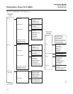
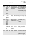
Sensor Heater
Malfunction
Transducer Block
1) O
2
Heater
Failure
2) Comb Heater
Failure
3) SB Heater
Failure
4) O
2
Heater
Ramp Rate
Exceeded
5) Comb Heater
Ramp Rate
Exceeded
6) SB Heater
Ramp Rate
Exceeded
7) Heater Relay
Failed
T/C Heater
Alerts
This alert
indicates that no
measurable heat
energy is being
detected at the
oxygen sensor or
that the heater
temperature is
rising too fast.
Check heater circuit
for lose or broken
connections, check
thermocouple wiring,
test or replace the
heater.
Mechanical or thermal stress may eventually
cause the sensor heater to fail. The resistance of
a properly functioning cell heater will measure
less than 100 ohms. A failed heater will generally
measure as an open circuit. Diagnosis must be
done at the analyzer. Refer to Section 8:
Troubleshooting for details.
The Heater Ramp Rate Exceeded problem is
usually caused by the inability of the device to
limit power to the heater. This could be caused by
a shorted triac component on the power supply in
the electronics stack. Diagnosis must be done at
the analyzer. Refer to Section 8: Troubleshooting
for details.
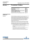
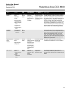
Sensor Heater
Over Temp-
erature
Transducer
Block:
1) O
2
Cell Temp.
Very High
2) Comb Temp.
Very High
3) SB Temp Very
High
TC Heater
Alerts
This alert
indicates a very
high heater
temperature;
temperature is
rising too fast.
Check heater wiring,
check thermocouple
wiring or replace the
electronics stack.
A heater over-temperature/out of control problem
would generally be caused by the inability of the
device to limit power to the heater. This could be
caused by a shorted triac on the power supply in
the electronics stack.
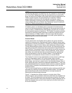
Sensor Heater
Temp-
erature Variance
Transducer
Block:
1) O
2
Cell Temp.
Low
2) O
2
Cell Temp.
High
3) Comb Temp.
Low
4) Comb Temp.
High
5) SB Temp.
Low
6) SB Temp.
High
T/C Heater
Alerts
This alert
indicates a
sensor heater
temperature that
is too high or too
low.
Allow instrument
several minutes to
reach proper
temperature or
check power supply.
Cell temperature control may become erratic for
the following reasons:
1) Temperature is settling during startup.
2) Large variations in process temperature or
flow.
3) Fluctuations or noise in the power supplied to
the instrument.
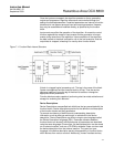
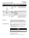
Calibration Error Transducer
Block:
1) O
2
Calibration
Failed
2) Comb
Calibration
Failed
3) Calibration
Warning
Calib-
ration
Alerts
This alert
indicates that the
slope and
constant values
determined from
the calibration did
not fall within an
acceptable
range.
Check the
calibration gas
supplies and
connections.
Make sure the oxygen concentrations of the
calibration gases match the concentration values
in the device. If the calibration has been
performed correctly this alarm may indicate that
the sensor requires replacement. Refer to
Section 8: Troubleshooting for details.
Calibration
Recommended
Transducer
Block:
Calibration
Recommended
Calib-
ration
Alerts
This alert
indicates that the
sensor resistance
has changed by a
predetermined
amount since the
last calibration.
Check instrument
accuracy and/or
calibrate.
Oxygen cells will degrade over time due to aging
and corrosion. An increasing cell resistance is a
good indicator of reduced cell performance. As
the cell impedance increases, the cell output falls
off and response time increases. Calibrating the
instrument will compensate for the increased cell
resistance. If using the device with an IMPS or
SPS calibration sequencer, increased cell
impedance can automatically trigger a calibration.
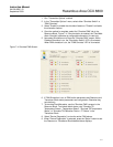
Alerts Alarms
AMS
Tab
What does the
alert indicate?
Recommended
Action
Description