


SECTION 7—WHEELS/FORKS
Part No 1118364 59 Spree XT
SECTION 7—WHEELS/FORKS
ƽ WARNING
After any adjustments, repair or service and BEFORE use, make sure all attaching
hardware is tightened securely - otherwise injury or damage may result.
Removing/Installing Rear Wheels
Quick-Release Axle
NOTE:Forthisprocedure,refertoFIGURE7.1.
NOTE:Toremoverearwheels,reversethisprocedure.
NOTE:Ifanyadjustments(sizeor position)to
therearwheelshavebeenmade,theanti‐tippers
mustbeadjustedtomaintainthe1‐1/2to
2‐inchclearance.Ifthisadjustmentcannotbe
madewiththeanti‐tipperscurrentlyinstalled,
adifferentmodelmayberequired.Consulta
qualifiedtechnicianforassistance.
1. Pushinthedetentpinofthe
quick‐releaseaxleandinsertthe
quick‐releaseaxlethroughthecenterof
therearwheel.
2. Pushinthetipofthequick‐releaseaxle
againandinserttheaxle(withwheel)
intotheaxlemountingplateontheside
ofthewheelchairframeuntilthe
assemblylocksinplace.
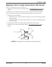
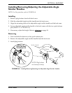
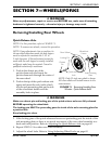
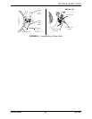
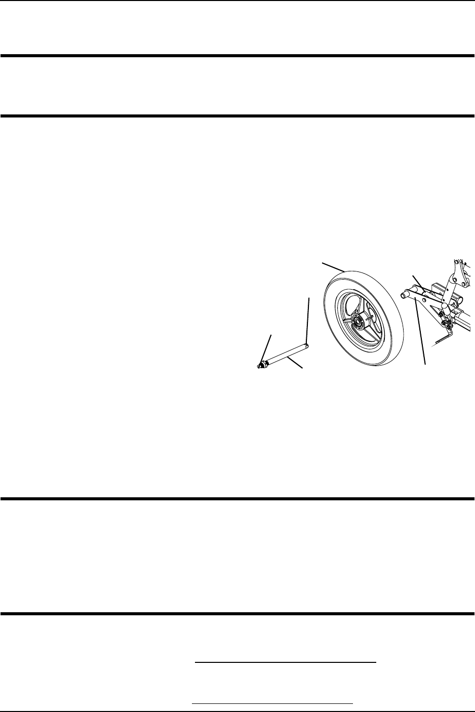
FIGURE 7.1 Removing/Installing Rear
Wheels - Quick-Release Axle
ƽ WARNING
Make sure detent pin and locking pins of the quick-release axles are fully released
BEFORE operating the wheelchair.
The locking pins MUST be protruding past the inside of the axle mounting plate for
a positive lock.
Keep locking pins clean.
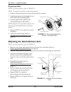
3. Ifthelockingpinsofthequick‐releaseaxlesarenotprotrudingpasttheinsideofthe
axlemountingplateorthereistoomuchmovementoftherearwheelassemblyina
backandforthposition.RefertoAdjustingtheQuick‐ReleaseAxle
onpage 60.
4. RepeatSTEPS1‐3forotherrearwheelassembly.
5. Adjustthewheellocks.RefertoUsing/AdjustingWheelLocksonpage 62.
Rear Wheel
Locking Pin
Detent
Pin
Quick-release
Axle
Axle Mounting
Plate
Wheelchair
Frame
NOTE:Only12‐inchrearwheelisshown.
Allotherwheelswillinstall/removeinthe
samemanner.