


SECTION 12—WHEELS
Power Tiger™ 84 Part No 1134839
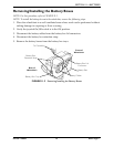
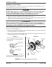
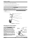
Installing the Drive Wheel
NOTE: Ensure keystock is in the cutout on the drive shaft (Detail “B” of FIGURE 12.3). The
keystock MUST line up with the wheel hub cutout.
CAUTION
DO NOT apply more than a 1-inch (in length) thin film of anti-seize compound to
the drive shaft. Applying more than 1-inch (in length) can cause the anti-seize
compound to leak resulting in damage to flooring (carpet, tile, etc.).
1. Apply an anti-seize compound to drive shaft and keystock.
2. Align the keystock in the drive shaft with the cutout in the wheel hub and position the
wheel on to the drive shaft (Detail “B” of FIGURE 12.3).
ƽ WARNING
Failure to properly install locking tab washer can result in wheel separation and
potential user injury or property damage. When replacing wheels, ALWAYS use a
new locking tab washer. DO NOT reuse locking tab washers.
NOTE: The locking tab of the locking tab washer MUST be inserted into the cutout in the rim and
hub (Detail “B” of FIGURE 12.3).
3. Using the mounting bolt, washer and new locking tab washer, secure the wheel to the
drive shaft (Detail “B” of FIGURE 12.3).
4. Fold one tab of the locking tab washer up so that the tab rests against one side of the
mounting bolt (Detail “A” of FIGURE 12.3).
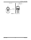
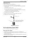
FIGURE 12.3 Removing/Installing the Rear Wheel
DETAIL “A”
DETAIL “B”
Locking Tab
Washers (Tabs)
Locking Tab
Washer (Tab)
Mounting Bolt
Mounting Bolt
NOTE: Locking tab washer shown with
all tabs folded down to remove/install the
mounting bolt.
NOTE: Locking tab washer shown with one
tab folded up to secure the mounting bolt.
Mounting
Bolt
Drive Shaft
Motor and
Gearbox
Washer
Keystock
Wheel
Outer Rim
Cutout
Locking
Tab
Locking Tab
Washer