


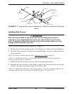
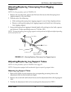
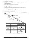

SECTION 6—SEAT ADJUSTMENTS
Part No 1114842 67 2G Tarsys®Powered Seating System
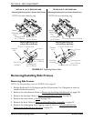
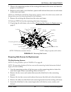
7. Observe the mounting position of the existing side frame to the center seat frame for
proper re-installation.
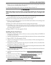
8. Remove two hex bolts, coved washers, spacers and locknuts that secure one side frame
to the center seat frame.
NOTE: For Tilt/Recline and Recline-Only seating systems, remove the socket screw, washer and
locknut that secure the connecting bracket to the crossbeam.
9. Remove the existing side frame from the center seat frame.
10. Perform STEPS 6-8 for the remaining side frame if necessary.
11. If replacing the side frame, refer to either Preparing Side Frames for Replacement on
page 67.
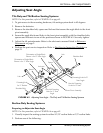
FIGURE 6.10 Removing Side Frames
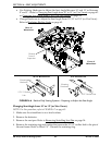
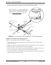
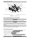
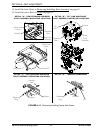
Preparing Side Frames for Replacement
Tilt-Only Seating Systems
NOTE: For this procedure, refer to FIGURE 6.11 on page 68.
NOTE: The mounting location of the hex screw on the connecting bracket determines the back
angle of the back assembly.
1. Note the mounting position of the hex screw on the connecting plate to obtain the
same back angle when re-assembling. Refer to Detail “A”.
2. Remove the hex screw and washer that secure the slide block to the connecting
bracket.
3. Remove the two hex screws and washers that secure the slide rod to the side frame.
4. Remove the slide rod, slide block and connecting bracket from the existing side frame.
5. Secure the slide block to the connecting bracket with the hex screw, washer, and
locknut.
Hex Bolt
Coved
Washer
Locknuts
Spacers
Hex Bolts
Coved
Washer
Hex Bolt
Coved Washer
Locknut
Spacer
Spacer
Locknut
Side Frame
Center Seat
Frame
NOTE: Tilt/Recline seat frame shown.
Crossbeam
Socket
Screw*
*NOTE: Only on systems with recline.
Connecting Bracket