


SECTION 5—INTERFACE HARDWARE
2G Tarsys®Powered Seating System 50 Part No 1114842
5. Perform one of the following:
• If the rear pivot assembly slide freely, proceed to STEP 6.
• If the rear pivot assembly is hard to move, repeat STEP 3 and STEP 4 until the rear
pivot assembly moves freely.
NOTE: It may be necessary to loosen the socket screws to adjust the linear guides.
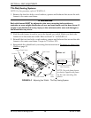
6. Torque the socket screws to 75 in-lbs ± 20%.
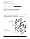
7. Align the front pivot assembly with the seat brackets.
8. Secure the front pivot assembly to the seat brackets in the location noted in STEP 1 of
Removing. Torque to 13 ft-lbs ± 20%.
9. Secure the front of the tilt actuator to the front pivot assembly using the shoulder
screw and locknut. Torque to 23 ft-lbs ± 20%.
10. Install the seat assembly. Refer to Removing/Installing the Seat
on page 75.
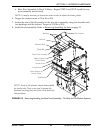
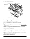
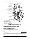
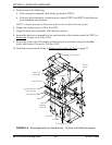
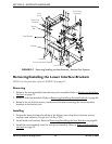
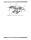
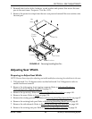
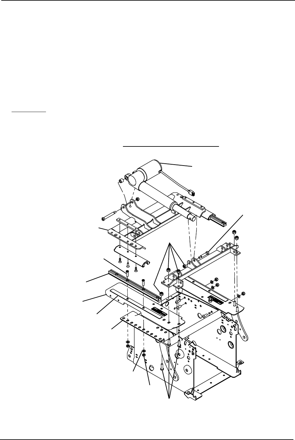
FIGURE 5.6 Removing/Installing the Seat Brackets - Tilt Only and Tilt/Recline Systems
Locknuts
Tilt Actuator
Socket
Screw
Lower Portion of
Linear Guide
Socket Screw
Locknut
Washer
Hex Screws
Rear Pivot
Assembly
Seat Bracket
Shim
Lower
Interface
Bracket