


SECTION 6—SEAT ADJUSTMENTS
Part No 1114842 63 2G Tarsys®Powered Seating System
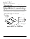
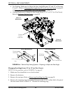
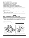
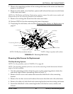
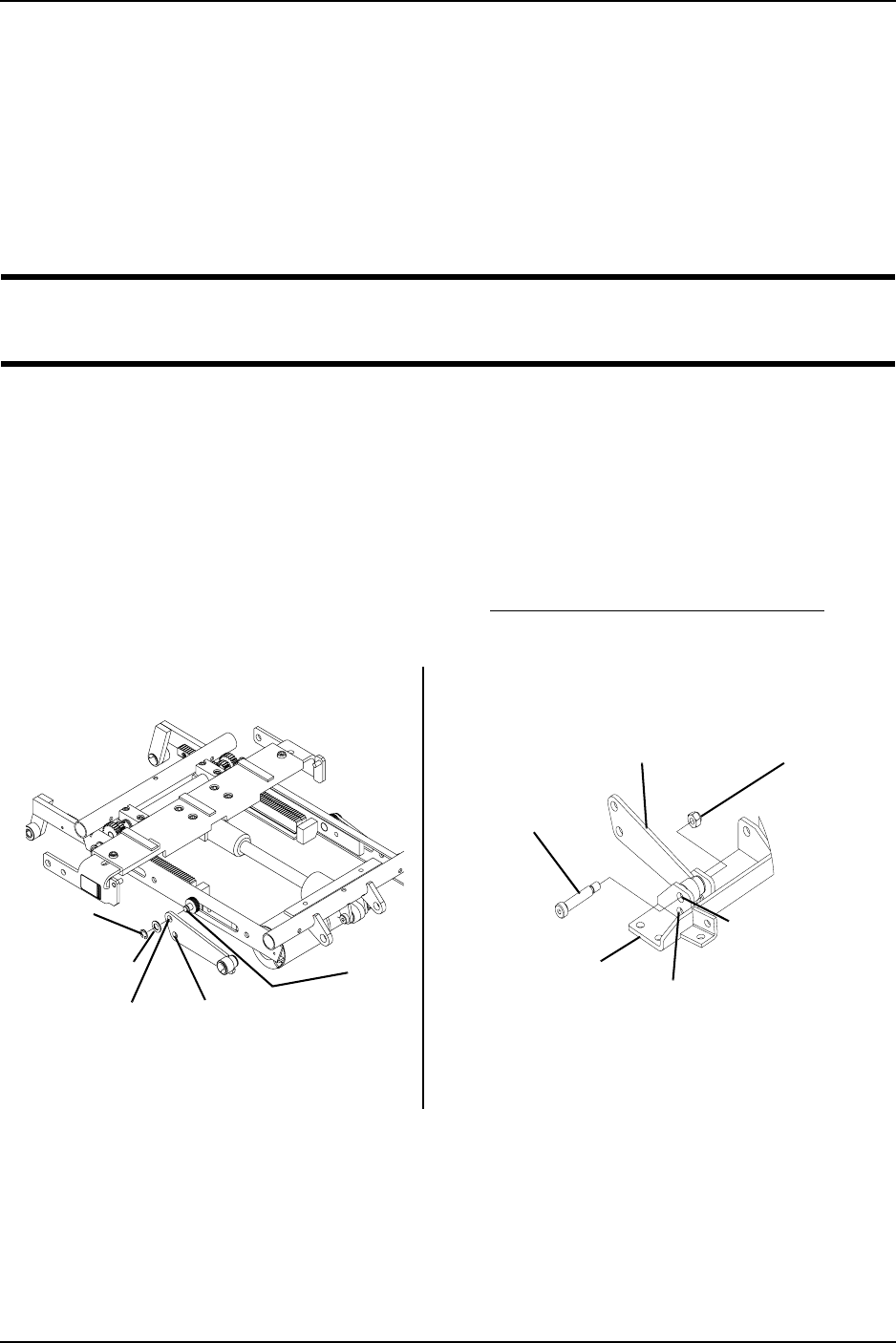
5. Remove the shoulder bolt and locknut that secure the 10°/15° recline link to the front
pivot assembly. Refer to Detail “B”.
6. Remove the recline link.
7. Reposition the recline link to the seat frame pin through the other mounting hole.
Refer to Detail “A” in FIGURE 6.7.
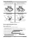
8. Secure the 10°/15° recline link to the seat frame pin with the washer and a new
retaining ring.
CAUTION
Be sure to use a new retaining ring that is not bent or damaged.
NOTE: When completed, verify that the retaining ring is fully seated in the groove in the pin.
9. Insert the existing shoulder bolt through the other mounting hole in the front pivot
assembly and then through the pivot hole in the recline link. Refer to Detail “B” in
FIGURE 6.7.
10. Securely tighten the locknut.
11. Repeat STEPS 4–10 for the opposite side.
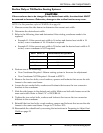
12. Perform the post-service inspection. Refer to Post-Service Inspection Checklist on
page 21.
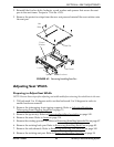
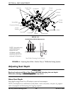
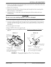
FIGURE 6.7 Changing Seat Angle from 10° to 15° (or Vice Versa)
Mounting Hole for
10° Seat Angle
Mounting Hole for
15° Seat Angle
Washer
*Retaining
Ring
*NOTE: Use
new retaining
ring.
DETAIL “A”
NOTE: Drawing shows attachment for 15°
seat angle as an example.
Pin
10° and 15°
Recline Link
Shoulder
Bolt
Front Pivot
Assembly
Locknut
Mounting Hole for
10° Seat Angle
Mounting Hole for
15° Seat Angle
DETAIL “B”
NOTE: Drawing shows attachment
for 15° seat angle as an example.