


Instruction Manual
IB-106-340CDR Original Issue
January, 2002
Rosemount Analytical Inc. A Division of Emerson Process Management Index 10-1
Hazardous Area Oxymitter DR
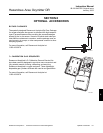
SECTION 10
INDEX
This index is an alphabetized listing of parts, terms, and procedures having to do with the Oxy-
mitter DR In-Situ Oxygen Probe. Every item listed in this index refers to a location in the manual
by one or more page numbers.
A
Abrasive Shield, 2-1, 2-3, 2-7
Absolute Temperature, 1-1
Adapter Plate, 1-2, 1-3, 2-1, 2-4, 2-5
Arithmetic Constant, 1-1
B
By-Pass Packages, 8-1
C
Calibration, 4-1
Calibration Gas, 1-3, 1-6, 2-2, 2-3, 4-1, 8-1
Calibration Gas Bottles, 1-8
Cell, 1-2, 4-5
Cell Constant, 1-1
Cell Replacement Kit, 7-2
Check Valve, 1-4
D
Diffusion Element, 1-2, 4-6, 4-8
Drip Loop, 2-6
E
Equipment Return, 6-1
H
Heater, 5-1
Heater Strut, 4-4
Heater Thermocouple, 1-2
I
Installation, Electrical, 2-7
Installation, Mechanical, 2-1
Installation, Pneumatic, 2-8
Instrument Air, 1-3, 2-8, 4-1
Insulation, 2-7, 4-1
M
Mounting, 1-6
N
Nernst Equation, 1-1
P
Packaging, 1-1
Partial Pressure, 1-1
Power Requirements, 1-6
Probe, 4-4, 7-1
Probe Disassembly Kit, 7-2
Probe Lengths, 1-2, 1-6
Process Temperature, 1-6
Product Matrix, 1-7
R
Reference Air, 1-3, 1-6, 2-2, 2-3
Reference Air Set, 1-2
Replacement Parts, Probe, 7-1
S
Specifications, 1-6
T
Terminal Block, 2-8, 4-1, 4-3
Thermocouple, Heater, 1-2
Troubleshooting, 5-1
V
Vee Deflector, 2-6
Z
Zirconia Disc, 1-1
10