


Instruction Manual
IB-106-340CDR Original Issue
January, 2002
Rosemount Analytical Inc. A Division of Emerson Process Management Maintenance and Service 4-7
Hazardous Area Oxymitter DR
g. If the contact assembly is damaged, replace
the strut or the contact pad. Instructions for
replacing the contact pad are in the cell re-
placement kit.
h. Remove and discard the corrugated seal.
Clean the mating faces of the probe tube
and retainer. Remove burrs and raised
surfaces with a block of wood and crocus
cloth. Clean the threads on the retainer and
hub.
i. Rub a small amount of anti-seize compound
on both sides of the new corrugated seal.
j. Assemble the cell and flange assembly, cor-
rugated seal, and probe tube. Make sure
the calibration tube lines up with the cali-
bration gas passage in each component.
Apply a small amount of anti-seize com-
pound to the screw threads and use the
screws to secure assembly. Torque to
4 N·m (35 in-lbs).
k. Install the termination housing per the
instructions in paragraph 4-5 steps c
through e.
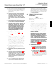
l. Apply anti-seize compound to the threads of
the cell assembly, hub, and setscrews. Re-
install the hub on the cell assembly. Using
pin spanner wrenches, torque to 14 N·m
(10 ft-lbs). If applicable, reinstall the vee de-
flector, orienting apex toward gas flow. Se-
cure with the setscrews and anti-seize
compound. Torque to 2.8 N·m (25 in-lbs).
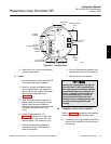
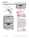
m. On systems equipped with an abrasive
shield, install the dust seal gaskets, with
joints 180° apart.
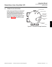
n. Reinstall the probe and gasket on the stack
flange.
o. Follow the instructions in paragraph 4-3b to
install the Hazardous Area Oxymitter DR
into the stack or duct. If there is an abrasive
shield in the stack, make sure the dust seal
gaskets are in place as they enter the 15°
reducing cone.
p. Turn on power and monitor thermocouple
output. It should stabilize at 29.3+0.2 mV.
Set reference air flow at 56.6 l/hr (2 scfh).
After the Hazardous Area Oxymitter DR sta-
bilizes, calibrate the unit. If new components
have been installed, repeat calibration after
24 hours of operation.
4-8 CERAMIC DIFFUSION ELEMENT
REPLACEMENT
NOTE
This refers to the ceramic diffusion
element only.
a. General
The diffusion element protects the cell from
particles in process gases. Normally, it does
not need to be replaced because the vee
deflector protects it from particulate erosion.
In severe environments, the filter may be
broken or subject to excessive erosion. Ex-
amine the ceramic diffusion element when-
ever removing the probe for any purpose.
Replace if damaged.
Damage to the ceramic diffusion element
may become apparent during calibration.
Compare probe response with previous re-
sponse. A broken diffusion element will
cause a slower response to calibration gas.
Hex wrenches needed to remove setscrews
and socket head screws in the following
procedure are available as part of a Probe
Disassembly Kit, Table 7-1.
b. Replacement Procedure
1. Follow the instructions in paragraph
4-3a to remove the Hazardous Area
Oxymitter DR from the stack or duct.
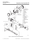
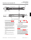
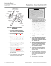
2. Loosen setscrews, Figure 4-5, using
hex wrench from Probe Disassembly
Kit, Table 7-1, and remove vee deflec-
tor. Inspect setscrews. If damaged, re-
place with stainless setscrews coated
with anti-seize compound.
4