


Instruction Manual
IB-106-340CDR Original Issue
January, 2002
2-10 Installation Rosemount Analytical Inc. A Division of Emerson Process Management
Hazardous Area Oxymitter DR
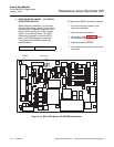
b. WESTINGHOUSE MODELS 218, 225,
AND 132 (ANALOG) ELECTRONICS
SETUP
Before beginning operation, it is important
that the probe heater setpoint of the existing
electronics be changed to support the Haz-
ardous Area Oxymitter DR In-Situ Oxygen
Probe. The setpoint adjustment procedure
required for Models 218, 225, and 132
analog electronics is as follows:
1. Open electronics enclosure.
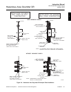
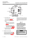
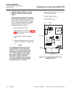
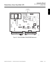
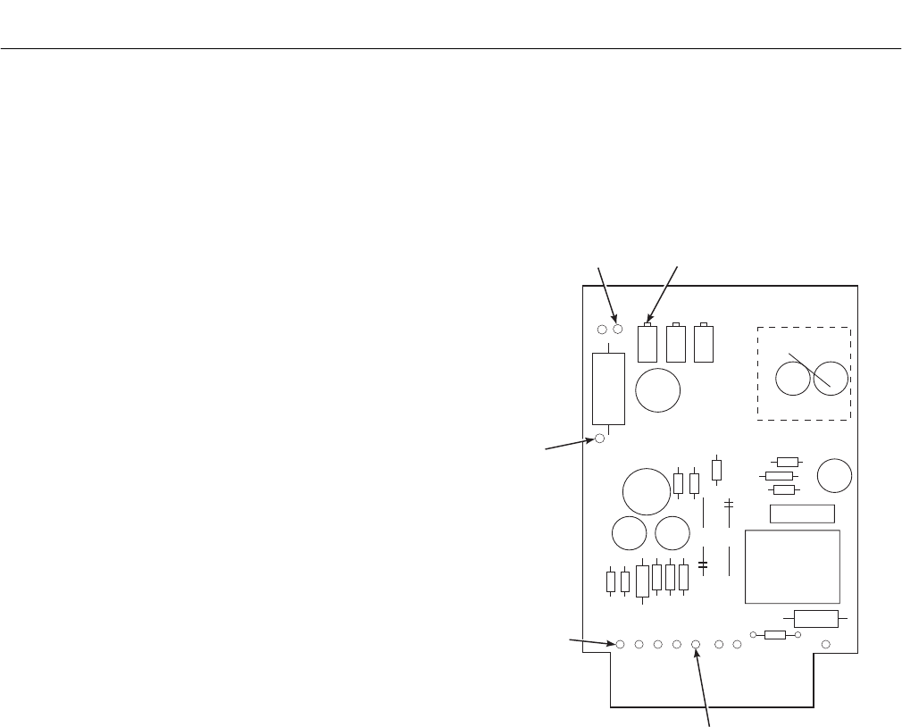
2. On temperature controller card, Figure
2-9, connect jumper wire from TP3 to
either Pin 2 or Pin 7.
3. Set voltmeter to read DC millivolts
(MV).
4. Attach voltmeter with positive (+) lead
on TP1 and negative (-) on either Pin 2
or 7.
NOTE
The voltage given above is for an am-
bient (machinery space) temperature
of 25°C (77°F). For each degree of am-
bient temperature above or below 25°C
(77°F), add or subtract 0.242 mV from
the nominal. Example: at 31°C (87°F),
the nominal voltage of -322.3 Mv
should be increased (made less nega-
tive) by 10 x 0.242 or 2.42 mV, making
the adjusted nominal -319.9 Mv.
5. Adjust potentiometer M110-1 to read -
322.3 millivolts nominal.
6. Remove voltmeter leads.
7. Remove jumper wire.
235671012
TP1
M110-1
TP3
PIN 2
(PSC)
PIN 7 (PSC)
P0019
Figure 2-9. Temperature Controller Card
Calibration Points