


Instruction Manual
IB-106-340CDR Original Issue
January, 2002
Rosemount Analytical Inc. A Division of Emerson Process Management Installation 2-1
Hazardous Area Oxymitter DR
SECTION 2
INSTALLATION
The Hazardous Area Oxymitter DR and
probe abrasive shield are heavy. Use
proper lifting and carrying procedures
to avoid personal injury.
Before installing this equipment, read
the “Safety instructions for the wiring
and installation of this apparatus” at
the front of this Instruction Bulletin.
Failure to follow safety instructions
could result in serious injury or death.
2-1 MECHANICAL INSTALLATION
If the probe will be installed into an existing lo-
cation, proceed to paragraph 2-1b.
a. Selecting Location
1. The location of the Hazardous Area
Oxymitter DR in the stack or flue is
most important for maximum accuracy
in the oxygen analyzing process. The
Hazardous Area Oxymitter DR must be
positioned so the gas it measures is
representative of the process. Best re-
sults are normally obtained if the Haz-
ardous Area Oxymitter DR is
positioned near the center of the duct
(40-60% insertion).
2. Longer ducts may require several Haz-
ardous Area Oxymitter DR units since
the O
2
can vary due to stratification.
3. A point too near the wall of the duct, or
the inside radius of a bend, may not
provide a representative sample be-
cause of the very low flow conditions.
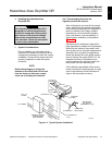
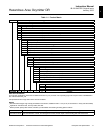
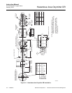
4. The sensing point should be selected
so the process gas temperature falls
within a range of 0° to 704°C (32° to
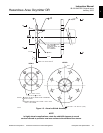
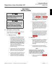
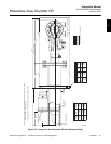
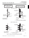
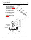
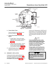
1300°F). Figure 2-1 through Figure 2-4
provide mechanical installation refer-
ences. The ambient temperature of the
termination housing must not exceed
65°C (149°F).
5. Ducts and stacks that operate under
negative pressure will draw air in
through any holes or torn seals, sub-
stantially affecting the oxygen reading.
Therefore, either make the necessary
repairs or install the Hazardous Area
Oxymitter DR upstream of any leak-
age.
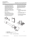
6. Ensure the area is clear of internal and
external obstructions that will interfere
with installation and maintenance. Al-
low adequate clearance for removal of
the Hazardous Area Oxymitter DR
(Figure 2-1).
b. Installation
1. Ensure all components are available to
install the Hazardous Area Oxymitter
DR. If equipped with the optional ce-
ramic diffusion element, ensure it is not
damaged.
2. The Hazardous Area Oxymitter DR
may be installed intact as it is received.
NOTE
An abrasive shield is recommended
for high velocity particulate in the flue
stream (such as those in coal-fired
boilers, kilns, and recovery boilers).
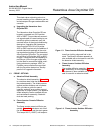
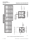
3. Weld or bolt adapter plate (Figure 2-4)
onto the duct.
2