


Instruction Manual
IB-106-340CDR Original Issue
January, 2002
Rosemount Analytical Inc. A Division of Emerson Process Management Maintenance and Service 4-3
Hazardous Area Oxymitter DR
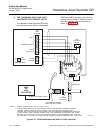
+
+
-
-
GROUND
LUGS
TYPE K
THERMOCOUPLE
SIGNAL
HEATER
POWER
TERMINAL
BLOCK
HEATER POWER
PORT
SIGNAL
PORT
LEFT SIDE OF
OXYMITTER DR
OXYGEN
SIGNAL
36210002
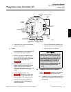
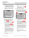
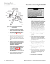
Figure 4-2. Terminal Block
8. Allow the unit to cool to a comfortable
working temperature.
b. Install.
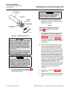
1. Bolt the Hazardous Area Oxymitter DR
to the stack and install insulation.
2. Insert the oxygen and heater thermo-
couple signal leads in the signal port
and connect to the oxygen and heater
thermocouple screw terminals
(Figure 4-2).
3. Insert the heater power leads in the
heater power port and connect to the
heater screw terminals. Slide the
heater terminal cover over the terminal
connection and tighten the cover
screw.
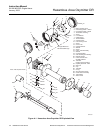
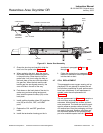
4. Install left housing cover (10,
Figure 4-1) and ensure it is tight. Se-
cure the cover using cover lock (11),
captive washer (13), and screw (12).
5. Connect the calibration gas and in-
strument air lines to the Hazardous
Area Oxymitter DR.
6. Turn on the calibration gases at the
cylinders and turn on instrument air.
7. Restore power to the system.
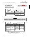
Opening the termination housing will
cause the loss of ALL hazardous per-
mits. Opening the termination housing
in hazardous areas may cause an ex-
plosion resulting in loss of property,
severe personal injury, or death. It
may be required to get a hot work
permit from your company safety offi-
cer before opening the electronic
housing.
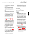
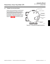
4-4 TERMINAL BLOCK REPLACEMENT
Refer to Figure 4-2 and perform the following
procedure to replace the terminal block.
a. Loosen the mounting screws on the termi-
nal block and carefully lift the block out of
the housing.
4