


Instruction Manual
IB-106-340CDR Original Issue
January, 2002
Rosemount Analytical Inc. A Division of Emerson Process Management Maintenance and Service 4-5
Hazardous Area Oxymitter DR
27540007
WIRE
LOOP
CERAMIC SUPPORT ROD
CELL FLANGE
HEATER
CERAMIC
DIFFUSER
ASSEMBLY
V-DEFLECTOR
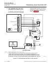
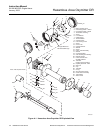
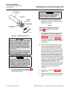
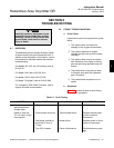
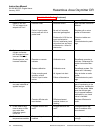
Figure 4-3. Heater Strut Assembly
f. Grasp the wire loop and carefully slide the
strut out of the probe tube (Figure 4-3).
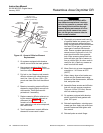
g. When replacing the strut, align the slot on
the heater plate with the calibration gas line
in the probe tube. Slide the strut into the
probe tube. It will turn to align the hole on
the back plate of the strut with the calibra-
tion gas line. When the hole and the cali-
bration gas line are aligned correctly, the
strut will slide in the rest of the way.
h. Push down on the back plate of the strut to
make sure you have spring tension and
then install the pressure clamp (28) on the
back plate.
i. Install capillary breather tubes (23) and tube
nuts (26) on the CAL, REF, and VENT
ports.
j. Replace the CAL and REF gas silicon
tubes.
k. Install the termination housing per the in-
structions in paragraph 4-5 steps c
through e.
l. Follow the instructions in paragraph 4-3b to
install the Hazardous Area Oxymitter DR
into the stack or duct.
4-7 CELL REPLACEMENT
This paragraph covers oxygen sensing cell re-
placement. Do not attempt to replace the cell
until all other possibilities for poor performance
have been considered. If cell replacement is
needed, order the cell replacement kit
(Table 7-1).
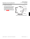
The cell replacement kit (Figure 4-4) contains a
cell and flange assembly, corrugated seal,
setscrews, socket head cap screws, and anti-
seize compound. The items are carefully pack-
aged to preserve precise surface finishes. Do
not remove items from the packaging until they
are ready to be used. Spanner wrenches and
hex wrenches needed for this procedure are
part of an available special tools kit (Table 7-1).
4