


Instruction Manual
IB-106-340CDR Original Issue
January, 2002
2-6 Installation Rosemount Analytical Inc. A Division of Emerson Process Management
Hazardous Area Oxymitter DR
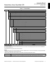
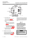
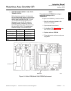
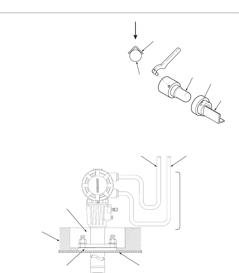
4. If using the optional ceramic diffusion
element, the vee deflector must be cor-
rectly oriented. Before inserting the
Hazardous Area Oxymitter DR, check
the direction of gas flow in the duct. Ori-
ent the vee deflector so the apex points
upstream toward the flow (Figure 2-5).
This may be done by loosening the
setscrews and rotating the vee deflector
to the desired position. Retighten the
setscrews.
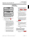
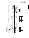
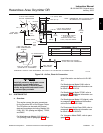
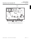
5. In vertical installations, ensure the sys-
tem cable drops vertically from the Haz-
ardous Area Oxymitter DR and the
conduit is routed below the level of the
termination housing. This drip loop
minimizes the possibility that moisture
will damage the electrical connections
(Figure 2-6).
VEE
DEFLECTOR
VEE
DEFLECTOR
DIFFUSION
ELEMENT
SETSCREW
FILTER
GAS FLOW
DIRECTION
APEX
22220020
Figure 2-5. Orienting the Optional Vee Deflector
P
S
U
E
I
T
P
I
C
R
H
W
E
N
T
H
G
C
K
E
N
I
-
E
E
R
W
A
V
I
S
O
L
P
-
X
O
M
T
A
G
N
I
N
-
R
I
T
L
A
I
V
E
-
E
E
H
GAS
CAL.
DRIP
LOOP
OXYGEN,
THERMOCOUPLE
SIGNAL
LINE
VOLTAGE
REPLACE INSULATION
AFTER INSTALLING
HAZARDOUS AREA
OXYMITTER DR
INSULATION
ADAPTER
PLATE
STACK OR DUCT
METAL WALL
36210007
Figure 2-6. Installation with Drip Loop and Insulation Removal