


Instruction Manual
IB-106-340CDR Original Issue
January, 2002
Rosemount Analytical Inc. A Division of Emerson Process Management Description and Specifications 1-1
Hazardous Area Oxymitter DR
SECTION 1
DESCRIPTION AND SPECIFICATIONS
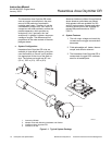
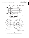
1-1 COMPONENT CHECKLIST OF TYPICAL
SYSTEM (PACKAGE CONTENTS)
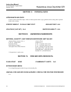
A typical Rosemount Hazardous Area Oxymitter
DR In-Situ Oxygen Probe should contain the
items shown in Figure 1-1. Record the part num-
ber, serial number, and order number for each
component of your system in the table located on
the back cover of this manual.
The Oxymitter DR is offered in both
hazardous and general purpose con-
figurations. The hazardous area ver-
sion has the “EX” and CSA symbols
on the apparatus approval label. The
general purpose version does not
have an approval label. If you received
the general purpose version, ensure
you do not install it in a potentially ex-
plosive atmosphere.
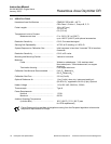
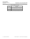
Also, use the product matrix in Table 1-1 at the
end of this section to compare your order num-
ber against your unit. The first part of the matrix
defines the model. The last part defines the
various options and features of the Hazardous
Area Oxymitter DR. Ensure the features and
options specified by your order number are on
or included with the unit.
1-2 SYSTEM OVERVIEW
a. Scope
This Instruction Bulletin is designed to supply
details needed to install, start up, operate,
and maintain the Hazardous Area Oxymitter
DR. The Hazardous Area Direct Replace-
ment Oxymitter can be interfaced to a num-
ber of different earlier model electronics
packages. These electronic packages are
not covered in this manual. For specification
information concerning calibration and op-
eration of the system, refer to the Instruction
Bulletin applicable to your electronics.
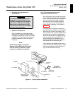
b. System Description
The Hazardous Area Oxymitter DR is de-
signed to measure the net concentration of
oxygen in an industrial combustion process;
i.e., the oxygen remaining after all fuels have
been oxidized. The probe is permanently po-
sitioned within an exhaust duct or stack and
performs its task without the use of a sam-
pling system.
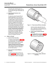
The equipment measures oxygen percent-
age by reading the voltage developed across
a heated electrochemical cell, which consists
of a small yttria-stabilized, zirconia disc. Both
sides of the disc are coated with porous
metal electrodes. When operated at the
proper temperature, the millivolt output volt-
age of the cell is given by the following
Nernst equation:
EMF = KT log
10
(P
1
/P
2
) + C
Where:
1. P
2
is the partial pressure of the
oxygen in the measured gas on
one side of the cell.
2. P
1
is the partial pressure of the
oxygen in the reference air on
the opposite side of the cell.
3. T is the absolute temperature.
4. C is the cell constant.
5. K is an arithmetic constant.
When the cell is at operating temperature
and there are unequal oxygen concentra-
tions across the cell, oxygen ions will travel
from the high oxygen partial pressure side to
the low oxygen partial pressure side of the
cell. The resulting logarithmic output voltage
is approximately 50 mV per decade. The
output is proportional to the inverse logarithm
of the oxygen concentration. Therefore, the
output signal increases as the oxygen con-
centration of the sample gas decreases. This
characteristic enables the Hazardous Area
Oxymitter DR to provide exceptional sensi-
tivity at low oxygen concentrations.
1