


Instruction Manual
IB-106-340CDR Original Issue
January, 2002
4-4 Maintenance and Service Rosemount Analytical Inc. A Division of Emerson Process Management
Hazardous Area Oxymitter DR
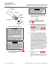
b. Carefully align the new terminal block on
the pins so that it sits flat in the housing.
The round end of the terminal block should
be on the opposite side of the housing con-
duit ports and should not be able to rotate.
c. Tighten the three mounting screws and en-
sure the terminal block is secure in the
housing.
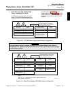
Opening the termination housing will
cause the loss of ALL hazardous per-
mits. Opening the termination housing
in hazardous areas may cause an ex-
plosion resulting in loss of property,
severe personal injury, or death. It
may be required to get a hot work
permit from your company safety offi-
cer before opening the electronic
housing.
4-5 ENTIRE PROBE REPLACEMENT
Do not attempt to replace the probe until all
other possibilities for poor performance have
been considered. If probe replacement is
needed, see Table 7-1 for part numbers.
a. Follow the instructions in paragraph 4-3a to
remove the Hazardous Area Oxymitter DR
from the stack or duct.
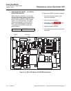
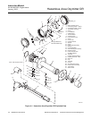
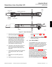
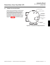
b. Remove four screws (15, Figure 4-1) and
washers (14). Separate the electrical con-
nectors between the heater strut assembly
and the electrical barriers on the termination
housing. The probe and termination housing
can now be separated.
c. When installing the new probe, make sure
that o-ring (27) is in good condition. Con-
nect the two electrical connectors between
the heater strut and the electrical barrier on
the termination housing. Make sure the
conduit port of the termination housing is on
the same side as the CAL and REF gas
ports.
d. Install the four washers (14) and screws
(15) and tighten.
e. Replace the housing cover (20) and ensure
it is tight.
f. Follow the instructions in paragraph 4-3b to
install the Hazardous Area Oxymitter DR
into the stack or duct.
4-6 HEATER STRUT REPLACEMENT
This paragraph covers heater strut replacement.
Do not attempt to replace the heater strut until
all other possibilities for poor performance have
been considered. If heater strut replacement is
needed, order a replacement heater strut (Table
7-1).
Use heat resistant gloves and clothing
when removing probe. Do not attempt
to work on the probe until it has
cooled to room temperature. The
probe can be as hot as 800°F (427°C).
This can cause severe burns.
a. Follow the instructions in paragraph 4-3a to
remove the Hazardous Area Oxymitter DR
from the stack or duct.
b. Remove four screws (15, Figure 4-1) and
washers (14). Separate the electrical con-
nectors between the heater strut assembly
and the electrical barriers on the termination
housing. The probe and termination housing
can now be separated.
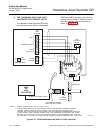
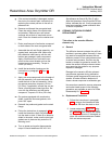
c. Once the probe and termination housing are
separated, spring tension releases and the
heater strut moves up. Carefully remove the
CAL and REF gas silicon tubes by pulling
them off the CAL and REF gas ports. Pull
the silicon tubes off the CAL and REF gas
lines.
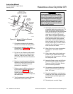
d. Remove pressure clamp (28).
e. Remove tube nuts (26), and capillary
breather tubes (23) from the CAL, REF, and
VENT ports.