


Instruction Manual
IB-106-340CDR Original Issue
January, 2002
2-14 Installation Rosemount Analytical Inc. A Division of Emerson Process Management
Hazardous Area Oxymitter DR
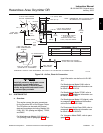
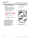
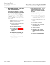
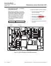
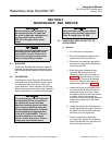
e. WESTINGHOUSE MODEL 132 DIGITAL
ELECTRONICS SETUP
Before beginning operation, it is important
that the probe heater setpoint of the existing
electronics be changed to support the Haz-
ardous Area Oxymitter DR In-Situ Oxygen
Probe. To convert the Model 132 Digital
Electronics Package for use with the DR
probe, an EPROM change is necessary.
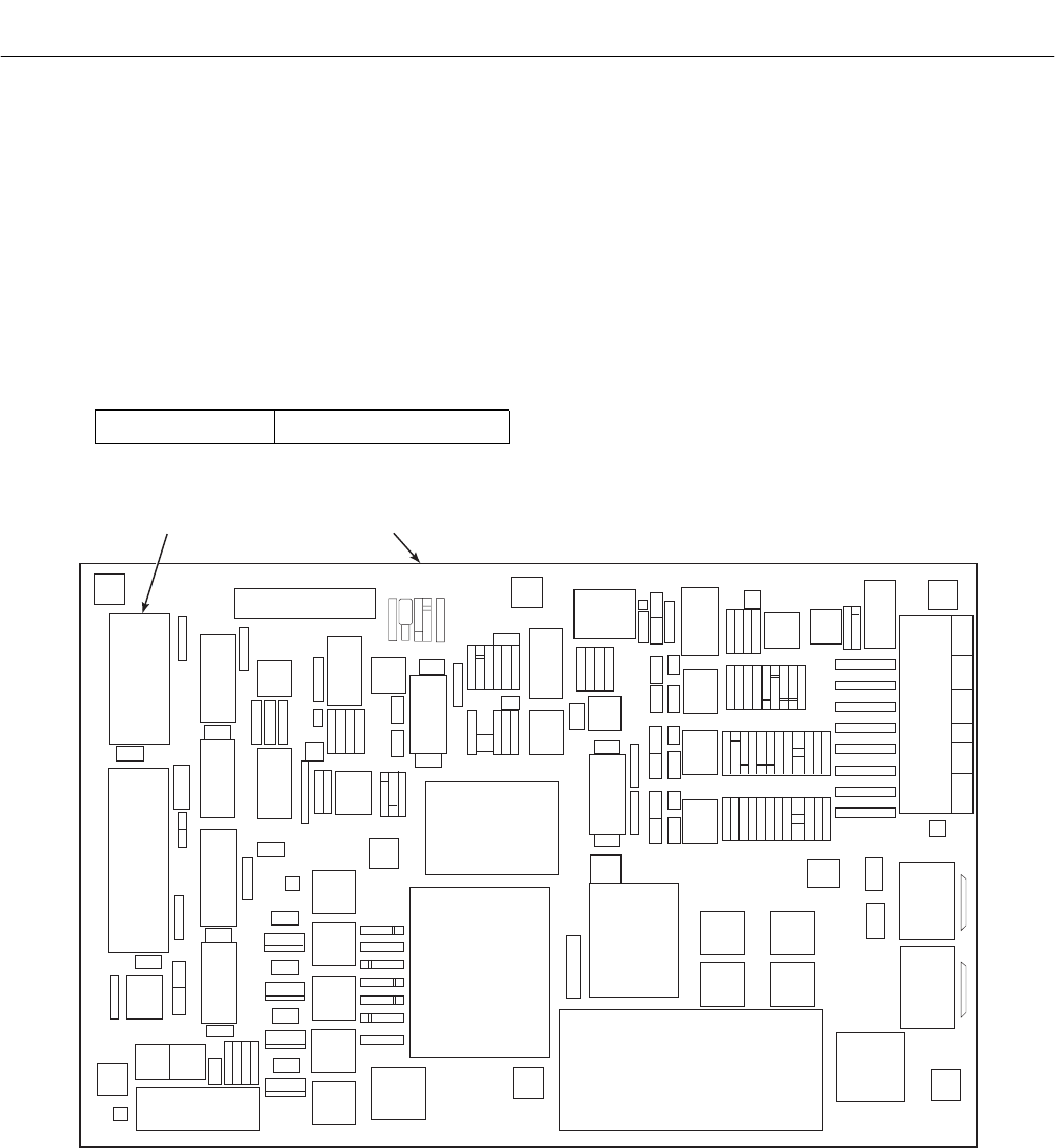
The replacement EPROM needed is as
identified below:
United States IM03222G01
To replace the EPROM, proceed as follows:
1. Shut off and lock out power to the
electronics package.
2. Open electronics enclosure.
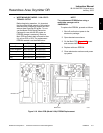
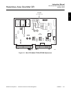
3. On the Main PCB, Figure 2-12, locate
and remove old EPROM.
4. Replace with new EPROM.
5. Close electronics enclosure and power
up system.
C13
28
28
28
28
28
28
28
28
C42
C43
LED1
U10
20
O18
P28
P61
R8
C48
U2
C44
U7
R27
XT1
C27
C26
U1
R38
C38
C37
C29
C28
LM8
04
03
TP1
J1
R48
C34
CR18
CR17
M55
C39
C30
R47
R49
R86
CR18
R38
R43
C10
U14
C31
C41
U3
R68
R64
P29
R61
P22
09
CR15
CR16
R42
U13
R41
R48
U9
R62
R63
R54
R53
08
1
RP1
R46
R48
P62
U12
C11
C48
C47
U2
C32
R9
C3
C2
C1
C4
C3 C8
C86
U11
C16
R6
C7
C8
C9
R44
TX2
CR19
R56
C38
C36
C7
U19
I
A
R1
P68
R59
R57
R58
CR9
R81
08
U17
U16
U18
R18
R16
R17
R19
CR8
CR5
CR6
CR7
R16
R18
CR4
CR3
R11
CR21
CR20
R14
R6
R23
R28
R7
C46
LK1
LK2
R4
CR2
CR1
R5
CR22
CR23
R2
R13
C17
R24
R21
R1
CK1
F1
F2
F4
F3
2001A
5A
5A
2001A
MOV1
MOV2
T83
C11
T82
ON
OFF
T81
SW1
FIL1
BR1
C10
D12
C13
R37
U4
C16
CR11
CR12
CR14
CR13
C12
C21
C46
C24
R12
C23
C22
D14
D13
U6
TP2
CR24
R36
TX1
R38
C30
CR25
P36
P25
C29
C14
D1
R26
D2
ALARM
MTR-T/C CELL SKG STK-T/C ML-O/P
E
E
L
L
N
N
HEATER
MAIN INPUT
TR1
MAIN PCB
EPROM
P0022
Figure 2-12. Main PCB (Model 132) EPROM Replacement