


Instruction Manual
Appendix A
January, 2002
A-2 Appendices Rosemount Analytical Inc. A Division of Emerson Process Management
Hazardous Area Oxymitter DR
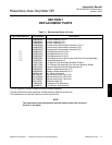
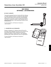
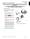
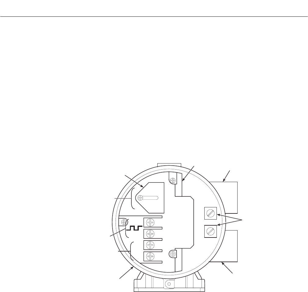
i. In the left side of the termination housing,
place the new termination designation la-
bels over the labels on the existing terminal
block. After placing the new labels, the ter-
minal block should appear as shown in
Figure A-2.
j. The existing wiring from the Oxymitter to the
electronics may be reused. However, the
wires will be carrying new signals as noted
by the new labels. The 4-20 mA wires must
be removed from the old electronics and re-
terminated to the wires carrying the 4-20
mA O
2
signal to the control room.
k. The wires carrying the heater power must
be converted to carry AC power (90-250
VAC, 50/60 Hz) for the Oxymitter. The re-
terminations may be inside the old elec-
tronics housing, which will function as a
simple junction box. Alternatively, the old
electronics may be removed and replaced
with a smaller junction box.
l. Place the round error blink code and cali-
bration instructions label on the inside of the
right housing cover.
m. Install both housing covers.
n. Refer to the instruction bulletin provided
with your upgrade kit, IB-106-340C, for
startup and diagnostic information.
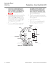
AC L1
AC N
+
+
-
-
4-20
GROUND
LUGS
LOGIC I/O OR
CALIBRATION HANDSHAKE
LINE VOLTAGE
(90 TO 250 VAC)
AC TERMINAL
COVER
TERMINAL
BLOCK
AC LINE
VOLTAGE PORT
SIGNAL
PORT
LEFT SIDE OF
OXYMITTER 4000
4-20 mA
SIGNAL
36210016
Figure A-2. Terminal Block and Wiring