


Instruction Manual
IB-106-340CDR Original Issue
January, 2002
Rosemount Analytical Inc. A Division of Emerson Process Management Description and Specifications 1-3
Hazardous Area Oxymitter DR
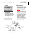
e. Handling the Hazardous Area
Oxymitter DR
The Hazardous Area Oxymitter DR is
designed for industrial applications.
Treat each component of the system
with care to avoid physical damage.
Some probe components are made
from ceramics, which are susceptible
to shock when mishandled.
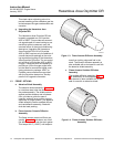
f. System Considerations
Prior to installing your Hazardous Area
Oxymitter DR, make sure you have all the
components necessary to make the system
installation. Ensure all the components are
properly integrated to make the system
functional.
NOTE
Retain the packaging in which the
Hazardous Area Oxymitter DR arrived
from the factory in case any compo-
nents are to be shipped to another
site. This packaging has been de-
signed to protect the product.
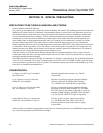
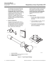
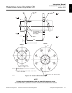
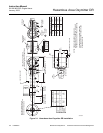
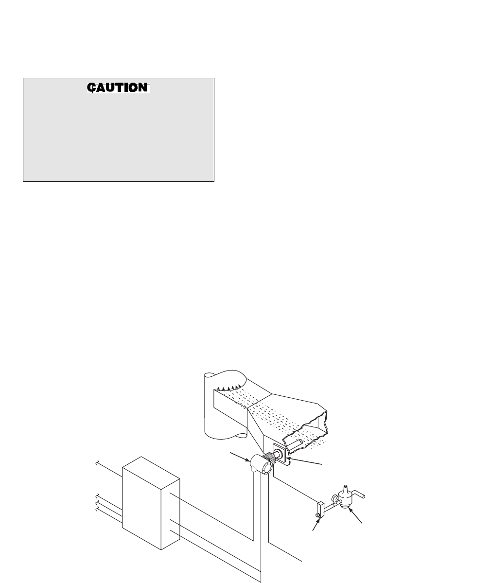
After verifying that you have all the compo-
nents, select mounting locations and deter-
mine how each component will be placed in
terms of available line voltage, ambient
temperatures, environmental considera-
tions, convenience, and serviceability. A
typical system installation is illustrated in
Figure 1-2.
Instrument air for reference is optional for
most applications. Ambient air will passively
diffuse into the inside of the probe in suffi-
cient quantity for an accurate measurement.
Instrument air is required for applications
where the ambient air at the probe location
may not contain the typical 20.95% O
2
. An
example would be an installation into a
positive pressure flue gas duct which has
many leaks into the surrounding air.
If the calibration gas bottles will be perma-
nently connected, a blocking valve or check
valve is required next to the calibration fit-
tings on the termination housing.
DUCT
STACK
GASES
CALIBRATION
GAS
ADAPTER
PLATE
HEATER
POWER
OXYGEN
SIGNAL
INSTRUMENT
AIR SUPPLY
(REFERENCE AIR)
PRESSURE
REGULATOR
FLOWMETER
OXYMITTER DR
36210004
THERMOCOUPLE
SIGNAL
EXISTING SIGNAL
CONDITIONING
ELECTRONICS
4-20 mA
SIGNAL
AC POWER
Figure 1-2. Typical System Installation
1