


Instruction Manual
IB-106-340CDR Original Issue
January, 2002
2-8 Installation Rosemount Analytical Inc. A Division of Emerson Process Management
Hazardous Area Oxymitter DR
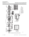
+
+
-
-
GROUND
LUGS
TYPE K
THERMOCOUPLE
SIGNAL
HEATER
POWER
TERMINAL
BLOCK
HEATER POWER
PORT
SIGNAL
PORT
LEFT SIDE OF
OXYMITTER DR
OXYGEN
SIGNAL
36210002
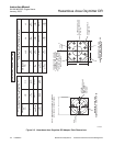
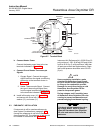
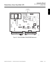
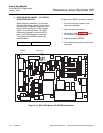
Figure 2-7. Terminal Block
b. Connect Heater Power
Connect the heater power lines to the two
terminals indicated in (Figure 2-7).
c. Connect O
2
and Heater Thermocouple
Signals
1. Oxygen Signal. Connect the oxygen
signal lines from the signal conditioning
electronics to the terminals shown in
Figure 2-7.
2. Heater Thermocouple Signal. Connect
the type K thermocouple signal lines
from the signal conditioning electronics
to the terminals indicated in Figure 2-7.
d. Install left housing cover (10, Figure 4-1)
and secure with cover lock (12), captive
washer (13), and screw (11).
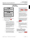
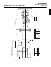
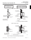
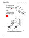
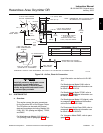
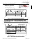
2-3 PNEUMATIC INSTALLATION
If instrument air will be used as reference air
(see System Considerations, paragraph 1-2f),
connect the reference air set to the Hazardous
Area Oxymitter DR. The reference air set should
be installed in accordance with Figure 2-8.
Instrument Air (Reference Air): 68.95 kPag (10
psig) minimum, 1551.38 kPag (225 psig) maxi-
mum at 56.6 L/hr (2 scfh) maximum; less than
40 parts-per-million total hydrocarbons. Regu-
lator outlet pressure should be set at 35 kPa
(5 psi).
NOTE
!
Upon completing installation, make
sure that the Hazardous Area Oxymit-
ter DR is turned on and operating prior
to firing up the combustion process.
Damage can result from having a cold
Hazardous Area Oxymitter DR ex-
posed to the process gases.
During outages, and if possible, leave
all Hazardous Area Oxymitter DR units
running to prevent condensation and
premature aging from thermal cycling.
If the ducts will be washed down dur-
ing outage, MAKE SURE to power
down the Hazardous Area Oxymitter
DR units and remove them from the
wash area.