


Instruction Manual
IB-106-340CDR Original Issue
January, 2002
Rosemount Analytical Inc. A Division of Emerson Process Management Maintenance and Service 4-1
Hazardous Area Oxymitter DR
SECTION 4
MAINTENANCE AND SERVICE
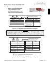
When working on this equipment on
the laboratory bench, be aware that
the probe, probe tube, and flame arre-
stor hub can be hot [up to 370°C
(698°F)] in the region of the probe
heater.
Install all protective equipment covers
and safety ground leads after equip-
ment repair or service. Failure to in-
stall covers and ground leads could
result in serious injury or death.
4-1 OVERVIEW
This section identifies the calibration methods
available and provides the procedures to main-
tain and service the Hazardous Area Oxymitter
DR.
4-2 CALIBRATION
The Hazardous Area Oxymitter DR should be
calibrated when commissioned. Under normal
circumstances the probe will not require fre-
quent calibration. When calibration is required,
follow the procedure described in the Instruction
Bulletin applicable to your electronics package.
It is recommended that the Hazardous
Area Oxymitter DR be removed from
the stack for all service activities.
Wear heat resistant gloves and cloth-
ing to remove probe from stack. Nor-
mal operating temperature of diffusor
and vee deflector are approximately
316 to 472°C (600 to 800°F). The unit
should be allowed to cool and be
taken to a clean work area. Failure to
comply may cause severe burns.
Disconnect and lock out power before
working on any electrical components.
There is voltage up to 115 VAC.
4-3 HAZARDOUS AREA OXYMITTER DR
REPLACEMENT
a. Remove.
1. Turn off power to the system.
2. Shut off the calibration gases at the
cylinders and the instrument air.
3. Disconnect the calibration gas and in-
strument air lines from the Hazardous
Area Oxymitter DR.
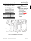
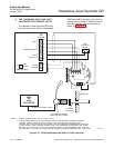
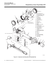
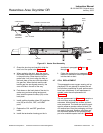
4. While facing the Hazardous Area
Oxymitter DR and looking at the
Rosemount label, remove screw (11,
Figure 4-1), captive washer (13) and
cover lock (12) securing left housing
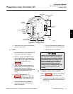
cover (10). Remove the cover to ex-
pose the terminal block (Figure 4-2).
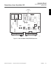
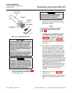
5. Loosen the screw on the heater termi-
nal cover and slide the cover back to
access the heater terminals. Loosen
the heater terminal screws and remove
the leads. Loosen the ground lug
screws and remove the leads. Slide the
heater power leads out of the heater
power port.
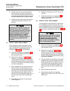
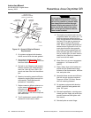
6. Loosen the oxygen and heater thermo-
couple signal terminal screws. Remove
the leads from the terminals and slide
the wires out of the signal port.
7. Remove insulation to access the
mounting bolts. Unbolt the Hazardous
Area Oxymitter DR from the stack and
take it to a clean work area.
4