


Instruction Manual
IB-106-340CDR Original Issue
January, 2002
4-6 Maintenance and Service Rosemount Analytical Inc. A Division of Emerson Process Management
Hazardous Area Oxymitter DR
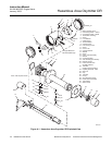
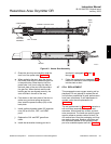
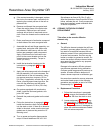
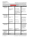
PROBE TUBE
(NOT INCLUDED
IN KIT)
SOCKET HEAD
CAP SCREWS
CORRUGATED
SEAL
CELL AND
FLANGE
ASSEMBLY
CALIBRATION GAS
PASSAGE
22220028
Figure 4-4. Cell Replacement Kit
Use heat-resistant gloves and clothing
when removing the probe. Do not at-
tempt to work on these components
until they have cooled to room tem-
perature. Probe components can be as
hot as 427°C (800°F). This can cause
severe burns.
Disconnect and lock out power before
working on any electrical components.
There is voltage of up to 115 VAC.
Do not remove the cell unless certain
it needs to be replaced. Removal may
damage the cell and platinum pad. Go
through the complete troubleshooting
procedure to make sure the cell needs
to be replaced before removing it.
a. Follow the instructions in paragraph 4-3a to
remove the Hazardous Area Oxymitter DR
from the stack or duct.
The flame arrestor and flame arrestor
hub are among the critical compo-
nents of this type of protection.
b. If the probe uses the standard diffusion
element, use a spanner wrench to remove
the diffusion element.
NOTE
To determine if the diffusion element
needs to be replaced, refer to para-
graph 4-1.
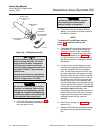
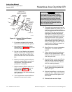
c. If equipped with the optional ceramic diffu-
sion assembly, remove and discard the
setscrews and remove the vee deflector
(Figure 4-5). Use spanner wrenches from
the probe disassembly kit (Table 7-1), to
turn the hub free from the retainer. Inspect
the diffusion element. If damaged, replace
the element.
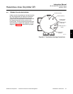
d. Loosen the four socket head cap screws
from the cell and flange assembly and re-
move the assembly and the corrugated
seal. The cell flange has a notch that may
be used to gently pry the flange away from
the probe. Note that the contact pad inside
of the probe will sometimes fuse to the oxy-
gen sensing cell. If the cell is fused to the
contact pad, push the cell assembly back
into the probe (against spring pressure) and
quickly twist the cell assembly. The cell and
contact pad should separate. If the contact
pad stays fused to the cell, a new
contact/thermocouple assembly must be in-
stalled. Disconnect the cell and the thermo-
couple wires at the probe electronics and
withdraw the cell with the wires still
attached.
e. Remove four screws (15, Figure 4-1) and
washers (14).
f. Separate the electrical connectors between
the heater strut and the termination hous-
ing.