


66
Reference Manual
00809-0200-4705, Rev AA
Appendix D: Mapping of Alert Messages in the HART
May 2015
Mapping of alert messages in the HART command 84
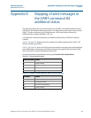
Table D-3. Failure Alerts (F:)
Message Additional Status
(1)
Description
Electronics Failure Byte 8 :: Bit 6 A failure has been detected in the device memory
and/or electronics
Configuration Error Byte 2 :: Bit 6 The device has detected a configuration error
based on a change to the device
Radio Failure Byte 1 :: Bit 6 The wireless radio has detected a failure or
stopped communicating
Supply Voltage Failure Byte 6 :: Bit 2 The supply voltage is too low for the device to
broadcast
(1) Location of the Alert in the HART command 48 Status field.
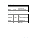
Table D-4. Maintenance Alerts (M:)
Message Additional Status
(1)
Description
Totalized Volume
Rollover
Byte 3 :: Bit 2 The totalized volume has exceeded the
maximum value and automatically reset to
zero
Average Flow Rate
Saturated
Byte 3 :: Bit 0 The average flow rate is beyond the operating
limits of the device and the reported value is
saturated
Electronics Temperature
Beyond Limits
Byte 8 :: Bit 5 The terminal temperature has exceeded the
transmitter’s maximum range
Supply Voltage Low Byte 8 :: Bit 4 The supply voltage is low and may soon affect
broadcast updates
(1) Location of the Alert in the HART command 48 Status field.