


37
Reference Manual
00809-0200-4705, Rev AA
Section 5: Operation and Maintenance
May 2015
Operation and Maintenance
5.5 Modbus
®
, EtherNet/IP and OPC mapping
Following is a table of parameters that can be used for Modbus, EtherNet/IP and OPC mapping.
These parameters are used by the Smart Wireless Gateway and can be found in the web
interface of the Gateway. Some of these parameters are analog values and some are discrete,
and this is noted in the description. The Setpoint parameters are used to drive the output
channel and for the readback of the state of the output channel.
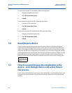
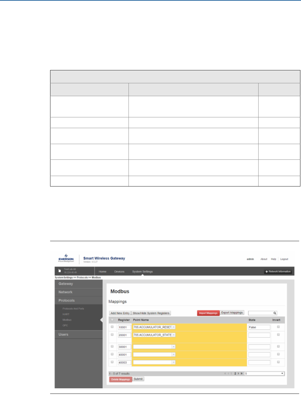
Mapping the Rosemount 705 parameters
Below is the Gateway screen where the accumulator reset, accumulator state, totalized_
volume, average_flow variables and parameter can be mapped. This is important to understand
how to reset the totalized volume of the device via Modbus, OPC, or EtherNet/IP
™
.
Figure 5-1. Smart Wireless Gateway Modbus Register Map
Parameters for Modbus, EtherNet/IP, and OPC Mapping
Parameter name Description Read/Write
SUPPLY_VOLTAGE Maps the supply voltage of the device. For
monitoring the health of your power module use
SUPPLY_VOLTAGE_HEALTHY
Read
ELECTRONICS_TEMPERATURE Maps the electronics temperature Read
TOTALIZED_VOLUME Maps the totalized volume that the device has
measured
Read
AVERAGE_FLOW_RATE Maps the instantaneous flow rate over that period
of time set by the DD
Read
ACCUMULATOR_RESET Use this parameter to reset the number of total
counts on the device
Write
ACCUMULATOR_STATE What is the current totalized value of the device Read