


14
Reference Manual
00809-0200-4705, Rev AA
Section 3: Mounting
May 2015
Mounting
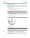
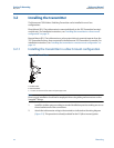
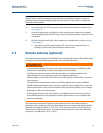
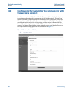
a. The antenna should be approximately 3-ft. (0.91 m) from any large structures or
buildings, to allow clear communication to other devices.
Figure 3-4. Antenna Positioning
3.2.2 Installing the transmitter in a remote mount configuration
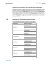
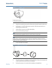
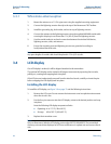
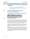
Figure 3-5. Remote Mount Installation
A. Turbine meter
B. Rosemount 705 Transmitter
C. 1-in. supplied cable gland adaptor for turbine meter.
Included:
(1) Cable gland
(1) Cable gland adaptor for turbine meter
10 ft. of cable connection wiring
1. Install the turbine meter or pulse output device according to standard installation
practices being sure to use thread sealant on all of the connections.
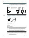
2. Pull the cable connection wiring through the supplied cable gland adaptor for the
turbine meter. Then pull the cable wiring through the transmitter cable gland.
Note
Pay attention to the orientation of the cable gland to ensure proper connection to transmitter.
3. Attach the turbine meter or pulse output device wiring to the terminals as shown in the
wiring diagrams beginning on page 8.
Possible antenna rotation shown.
Antenna rotation allows for best
installation practices in any
configuration.
A
B
C