2
Reference Manual
00809-0200-4705, Rev AA
Section 1: Introduction
May 2015
Introduction
1.2.1 Functions of the transmitter
Background of turbine meter operations
A turbine meter produces an accurate measurement that is achieved by using a bladed rotor
that turns at a speed proportional to rate of flow. The rotation of the rotor is sensed by electrical
pickoffs mounted on the meter body, generating a pulsing voltage. The total number of pulses
collected over a period of time represents the metered volume.
The Rosemount 705 Wireless Totalizing Transmitter’s primary function is to read the number of
pulses and then use this information to calculate flow and total volume. This information can
then be sent via WirelessHART
®
to the Gateway.
1.2.2 Wireless considerations
Power up sequence
The Smart Wireless Gateway should be installed and functioning properly before any wireless
field devices are powered. Install the Black Power Module, SmartPower
™
Solutions model
number 701PBKKF into the Rosemount 705 Transmitter to power the device. Wireless devices
should also be powered up in order of proximity from the Gateway, beginning with the closest.
This will result in a simpler and faster network installation. Enable Active Advertising on the
Gateway to ensure that new devices join the network faster. For more information see the Smart
Wireless Gateway Manual (document number 00809-0200-4420).
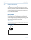
Antenna position
The antenna should be positioned vertically, either straight up or straight down, and it should be
approximately 3 ft. (1 m) from any large structure, building, or conductive surface to allow for
clear communication to other devices.
Figure 1-1. Antenna Position


