


12
Reference Manual
00809-0200-4705, Rev AA
Section 3: Mounting
May 2015
Mounting
3.2 Installing the transmitter
The Rosemount 705 Wireless Totalizing Transmitter can be installed in one of two
configurations:
Direct Mount (D1): The turbine meter is connected directly to the 705 Transmitter housing’s
conduit entry. For installation instructions, see “Installing the transmitter in a direct mount
configuration” on page 12.
Remote Mount (R1): The turbine meter or pulse output device is mounted separate from the
705 Transmitter housing, then connected to the Rosemount 705 Transmitter via conduit. For
installation instructions, see “Installing the transmitter in a remote mount configuration” on
page 14.
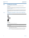
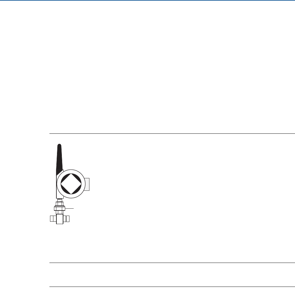
3.2.1 Installing the transmitter in a direct mount configuration
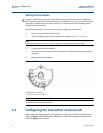
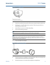
Figure 3-1. Direct Mount
A. Turbine meter
B. 705 Transmitter
C. 1-in. NPT connection to flow meter and 2 piece pipe union
Note
Direct mount installation should not be employed when using tubing and connectors such as
Swagelok
®
fittings.
1. Install the turbine meter according to standard installation practices making sure to use
thread sealant on all of the connections.
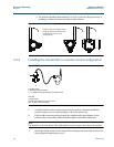
2. Attach the turbine meter wiring to the terminals as indicated on the wiring diagram
(Figure 3-2). This procedure is already included for the D1 (direct mount) option.
B
A
C