


13
Reference Manual
00809-0200-4705, Rev AA
Section 3: Mounting
May 2015
Mounting
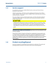
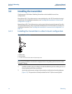
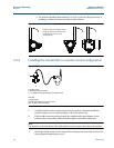
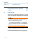
Figure 3-2. 705 Terminal Block
A. Pulse input connection
B. HART terminal connection
C. Terminal block ground connection
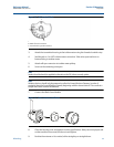
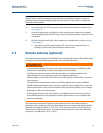
3. Attach the transmitter housing to the turbine meter using the threaded conduit entry.
4. Seal threads on 1-in. NPT turbine meter connection. Take union apart and turn on
bottom fitting to turbine meter.
5. Attach mill spec connector to turbine meter pickup.
6. Screw on the remaining union part.
Note
Sealant should already be applied to threads on the D1 (direct mount) option.
Note
Wireless devices should only be powered up after the Smart Wireless Gateway, in order of
proximity from the Smart Wireless Gateway beginning with the closest device. This results in a
simpler and faster network installation.
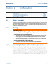
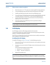
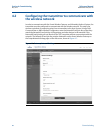
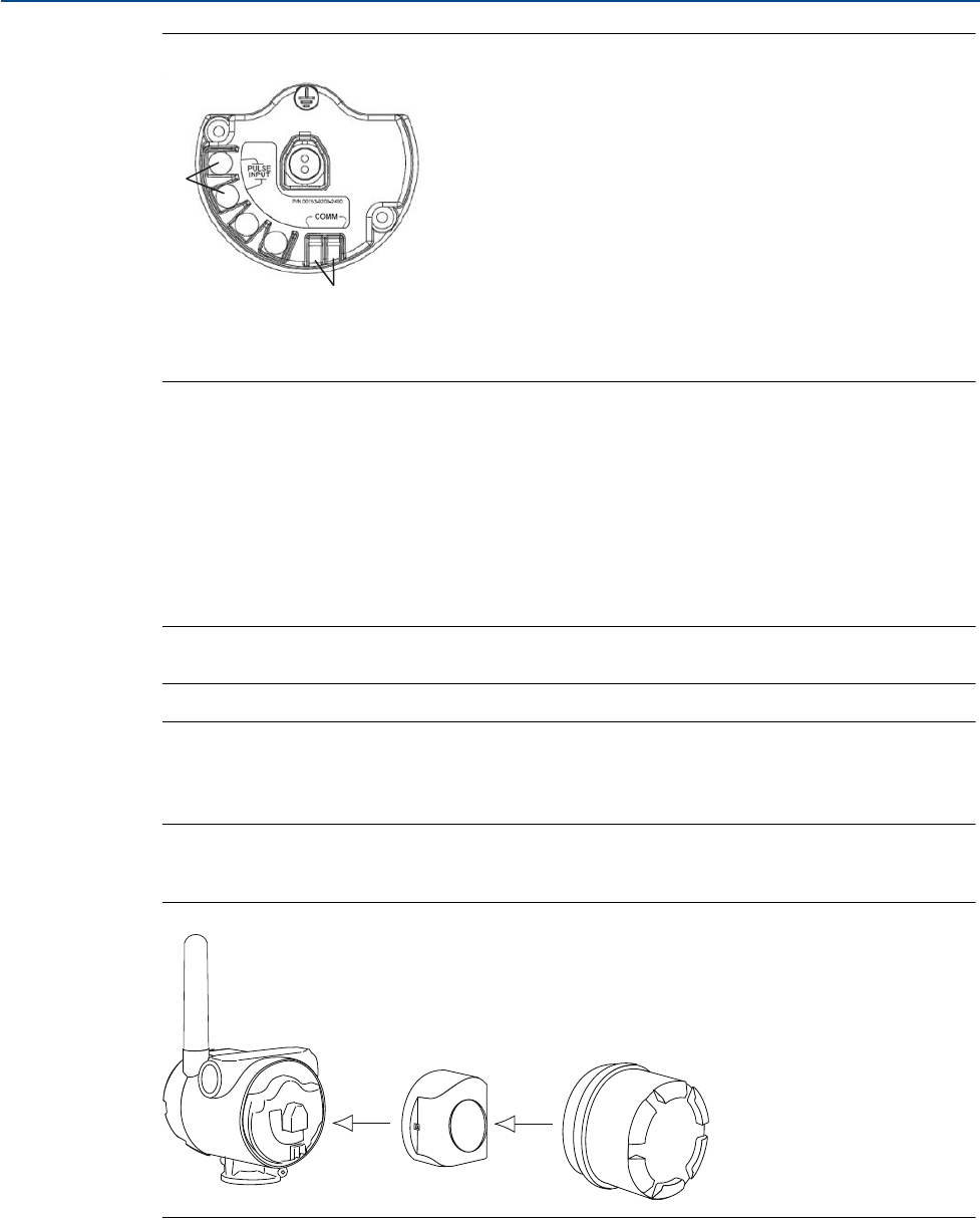
7. Connect the Black Power Module
Figure 3-3. Power Module Installation
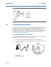
8. Close the housing cover and tighten to safety specification. Always ensure a proper seal
so that metal touches metal, but do not over tighten.
9. Position the antenna so it is vertical, either straight up or straight down.
A
C
B